 |
|||
|
|
|||
|
|
|||
| ||||||||||
|
|
 TM 9-4120-428-14
0016 00
INSTALLATION
Appropriate alterations to the facility to accommodate the selected method of installation must be completed before actual
installation of the air conditioner.
Shelter/Enclosure Preparation
The following information provides a typical through-the-wall type installation. Slightly altering these instructions may be
necessary in order to accommodate a specific application. WP 0059 00 provides a through-the-wall installation that allows
for the removal of the front and rear panels for service.
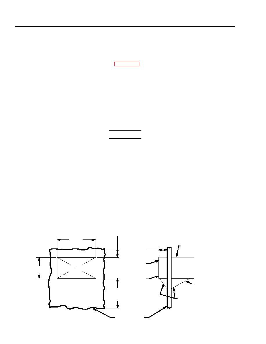
1. Determine best location for air conditioner and make a cutout in the wall, slightly larger than the dimension of the
air conditioner.
2. Fabricate a mounting platform or brace. Drill mounting holes to match the holes in the bottom of the air conditioner.
See illustrations in this work package for dimensions.
3. Use adequate equipment or at least four people to lift the air conditioner into position.
4. Secure the unit to the platform (or brace) with the mounting hardware provided with the unit. See WP 0000 00,
Sheet 3 for the cross section view of the bottom mounting holes and hardware.
WARNING
Severe injury or death may result if personnel fail to observe safety precautions. For safe
operation, connect a 10 AWG (minimum) ground wire to the air conditioner to ensure the
shelter is properly grounded.
1. Connect a 10 AWG (minimum) ground wire from the shelter ground to the air conditioner external ground. The air
conditioner external ground port is located on the front left side of the control module. See WP 0000 00.
2. Fill in and seal the area around the air conditioner to prevent the loss of conditioned air. Flexible plastic foam and
pressure sensitive tape may be used.
3. Fabricate an input cable of required length using the MS3106R18-11S connector, supplied with the air conditioner,
for connection to J1 or J11. (See chart below and Figure 4-4, Sheet 7). If J11 connector is used, be sure the wiring to
TB3 terminal board is relocated.
24 in.
(60.9 cm.)
SUGGESTED
FOR MAINTENANCE
23.8 in.
(60.6 cm.)
OUTSIDE
9.5 in.
(24.1 cm.)
16 in.
AIR CONDITIONER
SECTION
(40.6 cm.)
INSIDE
SHELTER
SIDE
VIEW FROM
FLOOR TO
INSIDE SHELTER
UNIT DISTANCE
PLATFORM OR
AS DESIRED
BRACES TO
SUPPORT AIR
CONDITIONER
TYPICAL WALL
0016 00-6
|
|
Privacy Statement - Press Release - Copyright Information. - Contact Us |
