 |
|||
|
|
|||
|
Page Title:
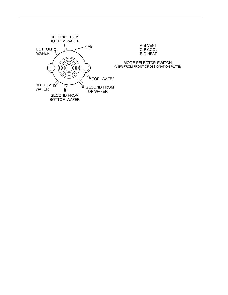
Figure 2. Mode Selector Switch |
|
||
| ||||||||||
|
|
 TM 9-4120-430-14
0026 00
Figure 2. Mode Selector Switch
DISASSEMBLY (Refer to Exploded View Figure 3)
NOTE
Disassembly should be limited to the replacement of defective parts.
1. Loosen setscrew on knob (3) and remove knob from mode selector switch (12).
2. Loosen setscrew on knob (4) and remove knob from potentiometer (15).
3. Remove four screws (5), four flat washers (7), and four lock washers (6), to open control box (9) and control panel
(8). Be careful of the wiring.
4. Remove mode selector switch S1 (12) from control panel (8) by removing nut (10) and star washers (11).
5. Remove temperature selector switch S2 (15) from control panel (8) by removing nut (13) and star washer (14).
6. If to be replaced after inspection and test, tag and disconnect wires (22) from defective mode selector switch S1 (12)
and temperature selector switch S2 (15).
7. Remove two nuts (19), two flat washers (18), two lock washers (17) and two screws (16), and connector P3 (21)
from control box (9).
8. Remove nut (27) to release ground wire. Remove wire ties (24) as required.
9. Leave insulation (30) and flexible tubing (23) and (31) in place unless damaged. If damaged, replace.
10. Leave stop nut (28) and lock washer (29) in place unless defective. If defective, replace.
0026 00-4
|
|
Privacy Statement - Press Release - Copyright Information. - Contact Us |
