 |
|||
|
|
|||
|
|
|||
| ||||||||||
|
|
 TM 9-4120-430-14
0031 00
3. If continuity is not indicated, repair or replace wire or damaged connector.
REMOVAL
1. Verify all labels on all wire leads prior to removal. Refer to wire lists (WP 0038 00).
2. Refer to WP 0029 00 for connectors J2 and J3 removal and WP 002700 for connector J1 removal.
3. Disconnect all terminals.
4. Carefully remove connectors from unit.
REPAIR
1. Remove the insulation to expose ‰ inch (1.27 centimeters) of bare wire on each side of break or damaged insulation.
2. Insert the ends into a splice-connector, splice and crimp the connector to make firm electrical contact.
3. Alternatively, heat-shrink tubing may be slipped over one end of the wire before splicing, then heated after the splice
is made and soldered, so as to cover the spliced area.
4. Be sure that no bare wire is exposed after splice is complete.
5. Replace broken terminal lugs with exact duplicates.
6. Check continuity terminal-to-terminal.
INSTALLATION
1. Install new labels on new wires. Refer to wire lists (WP 0038 00).
2. Install connectors (J1 and J2). Refer to WP 0029 00.
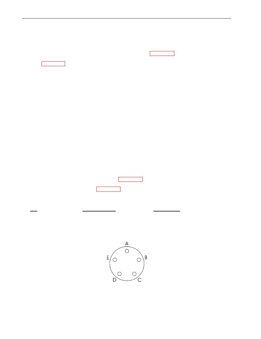
Pin Assignments for S9150-18KH-1 (Figure 1)
PIN
1-PHASE POWER
WIRE COLOR
A
LINE A
BLACK
B
LINE B
RED
D
NEUTRAL
(NOT USED)
E
GROUND
GREEN
Figure 1. S9150-18KH-1 Pin Assignments for J1 and J2 Connectors
0031 00-2
|
|
Privacy Statement - Press Release - Copyright Information. - Contact Us |
