 |
|||
|
|
|||
|
|
|||
| ||||||||||
|
|
 TM 10-4110-262-13&P
0020 00
9. Tag and disconnect the wires from the terminals.
10. Connect the tagged wire ends to the replacement connector, ensuring that the terminals to which the
wires connect correspond to the same terminals on the connector that was replaced. Make sure the
terminal screws are secure.
11. Verify the gasket is serviceable. If not, replace or seal with sealant to ensure a watertight seal.
12. Replace the cover plate and screws removed in Step 2.
13. Connect a 110 VAC 50-60 Hz power supply to the power input connector and test the operation of the
IC electrical system as described in Work Package 0018 00.
REPLACE
Power Entry Connector Receptacle Box
1. Ensure power is disconnected.
2. Remove receptacle from the receptacle box.
3. Tag wires and remove them from the receptacle.
4. Cut the sealant from around the receptacle box.
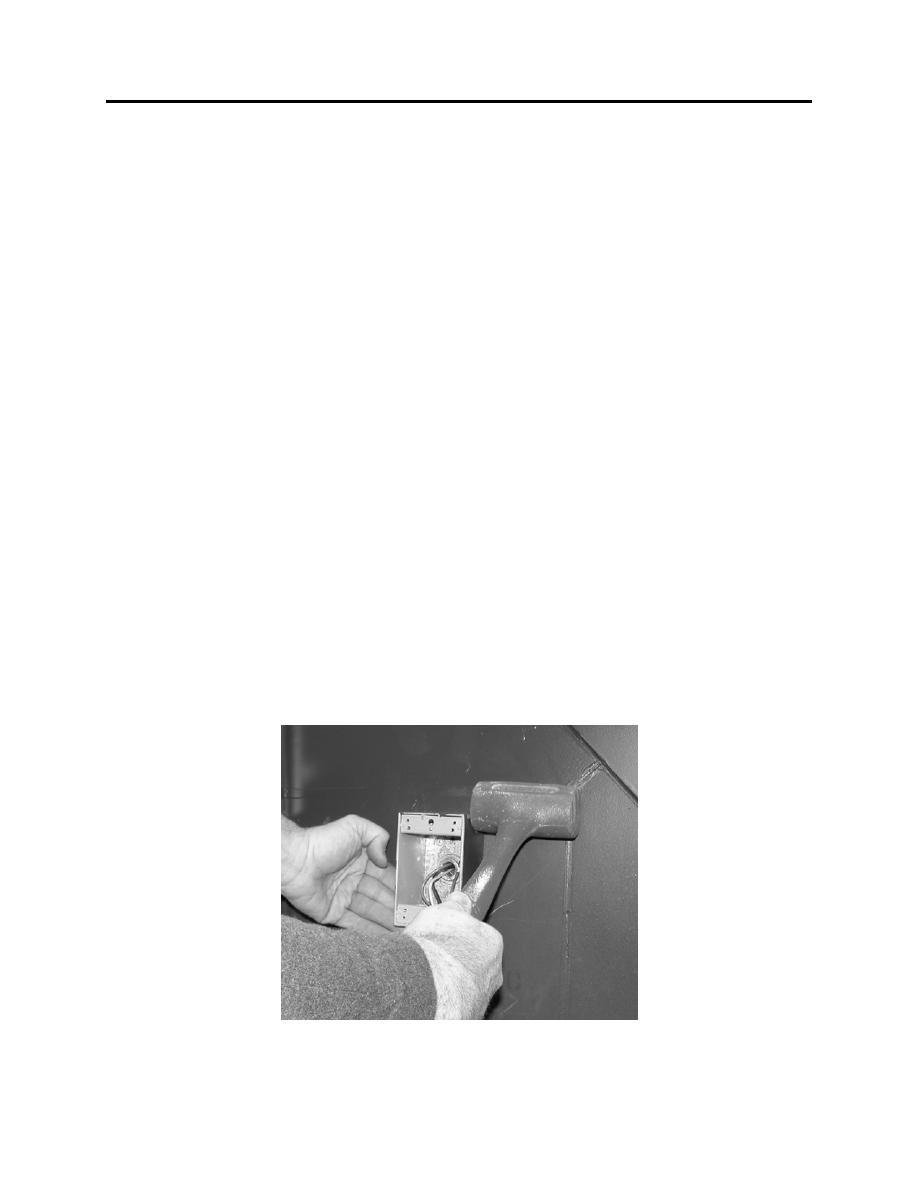
5. Remove the two fasteners from the back of the box on the IC.
6. Use a mallet to rotate the receptacle box counter-clockwise. Remove the receptacle box.
0020 00-3
|
|
Privacy Statement - Press Release - Copyright Information. - Contact Us |
