 |
|||
|
|
|||
|
Page Title:
Section XV. CONTROLS AND INSTRUMENTS |
|
||
| ||||||||||
|
|
 TM 5-4110-217-14
1.
Fan, condenser
8.
Washer
14.
Key, pulley
19A.
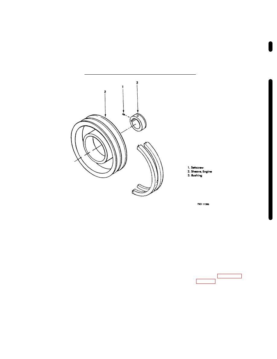
Setscrew
25.
Fitting, grease
2.
Setscrew
9.
Nut
15.
Clutch, magnetic
20.
Bearing, fan shaft 26.
Tubing, lube
3.
Fan, evaporator
10.
Belt, alternator drive
16.
Screw
21.
Screw, hex
27.
Coupling
4.
Setscrew
11.
Belt, fan drive
17.
Washer
22.
Bolt, elevator
28.
Sheave, Engine
5.
Key
12.
Belt, compressor drive
18.
Bracket
23.
Washer, lock
29.
Setscrew
6.
Tensioner, belt
13.
Shaft, fan
19.
Pulley, fan drive
24.
Nut, hex
7.
Screw
Figure 3-21 - Continued
Figure 3-22. Sheave and B
Section XV. CONTROLS AND INSTRUMENTS
These are an over-crank-limit safety relay, starter relay,
3-55.
General.
And defrost relay.
a. The major controls and instruments consist of
c. A thermometer, compound pressure gage, and
a control box assembly which includes an hourmeter,
high pressure gage are mounted on left side of the front
ammeter, thermostat, defrost timer, on-off switch,
refrigeration unit chassis frame.
manual-start frost push switch, indicator lights, fuse
holder and fuse. These items are mounted on the front
3-56.
Control Box Assembly Removal.
panel of the control box.
b. Three plug-in relays are mounted on a printed
a. Remove six screws(5, fig.
3-24) holding
control box assembly (6, fig. 3-24) to unit.
circuit board on the back inside of the control box.
Change 3 3-31
|
|
Privacy Statement - Press Release - Copyright Information. - Contact Us |
