Order this information in Print

Order this information on CD-ROM

Download in PDF Format


Click here to make tpub.com your Home Page

Page Title: Figure 5-7. Charging valves and pressure switch connections
Back | Up | Next

Click here for a printable version

Google


Web
www.tpub.com

Home


Information Categories
.... Administration
Advancement
Aerographer
Automotive
Aviation
Combat
Construction
Diving
Draftsman
Engineering
Electronics
Food and Cooking
Math
Medical
Music
Nuclear Fundamentals
Photography
Religion
USMC
   
Products
  Educational CD-ROM's
Printed Manuals
Downloadable Books


b.  Installation.   Install  high  and  low  pressure cutout  switches  as  follows: 
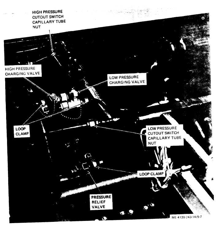
(1)   Insert   capillary   tube   ends   through   par- tition  and  install  grommet.  Connect  capillary  tube nuts  (fig.  5-7)  to  fittings. (2) Install switches (fig. 4-21) and secure each with  two  screws  and  lock  washers. (3)   Make   electrical   connections   to   switches. Figure 5-7. Charging valves and pressure switch connections. (4)   Refer   to   paragraph   4-54   and   install junction  box.  Refer  to  paragraph  4-21  and  install housing  top  covers. (5)  Refer  to  paragraph  6-3  and  charge  the refrigerant system. 5-22.  Charging  Valves a.  Removal.  Refer   to   paragraph   6-3   and 5-11

Privacy Statement - Press Release - Copyright Information. - Contact Us - Support Integrated Publishing

Integrated Publishing, Inc. - A (SDVOSB) Service Disabled Veteran Owned Small Business