|
| |
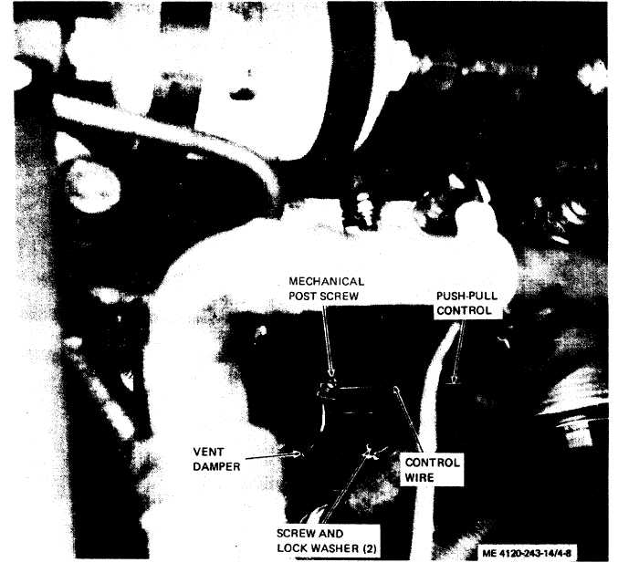
Figure 4-8. Vent damper.
b. The control should be adjusted for the center
position between open and closed. The actuator
should then be in the centered position and the rod
on top of the dam per should be parallel with front
of the housing.
c. Check operation. The control should move
smoothly between the open and closed position.
4-28. Removal.
a. Vent Damper. Refer to paragraph 4-21 and
remove the housing covers. Refer to figure 4-8 and
remove vent damper as follows:
(1) Loosen screw on mechanical post and
disconnect push-pull control.
(2) Remove two screws and lock washers and
lift vent damper from air conditioner.
b. Push-Pull Control. Refer to paragraph 4-18
and remove evaporator louvers. Refer to figures 4-7
and 4-8 and remove push-pull control as follows:
(1) Remove screw, washer, nut, spacer and
loop clam p.
(2) Loosen screw on mechanical post to free
end of control wire core.
(3) Remove outer nuts from both ends of
control outer casing and remove push-pull control.
c. Vent Control Actuator. Refer to figure 4-7 and
remove screw, nut, two spring washers and ac-
tuator.
4-16
|