|
| |
TM 5-4120-259-15
WARNING:
BE SURE TO USE A WELL
INSULATED SCREWDRIVER
WITH CAUTION WHILE
ADJUSTING.
STEP 1.
STEP 2.
STEP 3.
STEP 4.
STEP 5.
STEP 6.
NOTE:
STEP 7.
REMOVE ELECTRICAL JUNCTION BOX (FIG. 19).
CONNECT MAIN POWER CONNECTOR.
TURN ROTARY CONTROL SWITCH TO COOL AND NOTE TIME LAPSE BETWEEN STARTING
OF CONDENSER FAN AND STARTING OF COMPRESSOR. (PROPER TIME LAPSE IS FROM
4 TO 18 SECONDS).
IF TIME LAPSE IS LESS THAN 4 SECONDS, TURN CONTROL SWITCH OFF AND TURN T IME
DELAY ADJUSTING SCREW ONE TURN COUNTERCLOCKWISE.
WAIT 3 MINUTES AND REPEAT STEP 3.
IF TIME LAPSE IS MORE THAN 18 SECONDS,
TURN ADJUSTING SCREW ONE TURN CLOCKWISE.
WAIT 3 MINUTES AND REPEAT STEP 3.
CONTINUE ADJU5TING UNTIL PROPER TIME
LAPSE IS REACHED.
PROPER TIME LAPSE AT 150° IS 7 SECONDS ±3, AT 100° IT IS 10 SECONDS ±3, AND
AT 50°, IT IS 15 SECONDS ±3.
UNPLUG POWER CONNECTOR AND INSTALL ELECTRICAL JUNCTION BOX (FIG. 19).
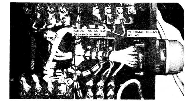
Figure 23. Thermal Delay Switch Adjustment.
35
|