|
| |
TM 5-4120-270-15
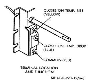
Figure 6-3. Temperature control thermostat test points.
Caution: Do not apply test potentials
in excess of 230 volts
(d) Energize control coil using a 2428V DC
source or two 12 volt batteries connected in series.
Using a multimeter on lowest OHMS range, test contact
resistance across each pair of line and load terminals L,-
T,, L2-T, and L,-T,. Contact resistance in excess of 0.2
ohms indicates dirty or burnt contacts. Clean contacts if
possible, or replace contactor.
(2) 25-ampere contactors. Proceed as instructed
above, noting that line and load terminals are now Al-A2,
B1-B2 and C1-C2. Observe same cautions.
e. Reassembly. Reassemble any parts that were
removed for cleaning or dressing contacts.
f. Installation. Refer to figure 6-4 and install
contactors in junction box.
6-6. Time Delay Relay
a. General. The time delay relay is a hermetically
enclosed,
single-pole,
single-throw
normally
open
thermal delay relay which keeps the hot gas bypass
valve open and prevents operation of the compressor for
30 seconds after the selector switch is placed on
"COOL". The time delay relay closes at the end of the
delay period and remains closed as long as the air
conditioner is on "COOL" mode. Switching to other
modes of operation opens the relay. It remains open
until the air conditioner is again placed on "COOL" mode,
at which time it delays valve and compressor operation
as outlined above.
b. Removal. Refer to figure 6-4 and remove the time
delay relay assembly from the junction box.
c. Disassembly. Do not disassemble for testing. If
replacement is indicated, remove time delay relay from
its mounting bracket and disconnect electrical leads.
d. Testing.
(1) Refer to figure 6-7 and place a continuity
indicator or multimeter on low OHMS range across leads
A and B.
(2) Apply 2-28V DC from a test source or two
12-volt batteries in series across leads A and C.
(3) Begin timing the relay from the instant DC
power is applied until the continuity indicator or
multimeter indicates the relay contacts have closed.
Normal delay is 30 seconds :8 seconds. Replace time
delay relay if delay time is not according to specifications.
e. Reassembly. Connect electrical leads to time
delay relay and mount relay in its bracket.
f. Installation. Refer to figure 64 and install time
delay relay in the-junction box.
6-7. Transformer
a. General. The control circuit transformer is a
single-phase, shielded, potted stepdown transformer with
a 208V AC primary and a 30V AC secondary. After
rectification, the resulting 24V DC output is used to
energize the magnetic contactor and solenoid valve
control coils and the time delay relay. The transformer
primary circuit is protected by the auxiliary circuit breaker
contact and by a cartridge-type fuse in each line.
b. Removal. Refer to figure 64 and remove the
transformer from the junction box.
c. Disassembly. Disconnect electrical leads from
primary and secondary terminals. Do not disassemble
further.
d. Testing.
(1) Connect a continuity tester or multimeter
on low OHMS range across the transformer primary
winding. If winding is open, replace transformer.
(3) Connect a continuity tester or multimeter
on low OHMS range across the transformer secondary.
If winding is open, replace transformer.
(3) Connect an insulation tester, megger or
multimeter on high OHMS range between one primary
terminal and transformer, case. If resistance is less than
0.5 megohm,-replace transformer.
(4) Connect an insulation tester, megger or
multimeter on high OHMS range between one primary
terminal and one secondary terminal. If resistance is
6-4
|