|
| |
TM 5-4120-270-15
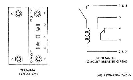
Figure 6-5. Circuit breaker test points.
b. Removal. Refer to figure 6-4 and remove the RFI
filter assembly from the side of the junction box.
c. Disassembly. Refer to figure 3-7 and disassemble
RFI filter assembly into components.
d. Testing.
(1) Rectifier.
(a) Using a multimeter on DC VOLTS range
measure rectifier output voltage across positive and
negative terminals when 28V AC is applied to the AC
terminals through a stepdown transformer. Rectifier
output should measure 24 “5V DC. Replace rectifier if
output voltage is less than specified.
(b) Using a multimeter on OHMS range
measure rectifier resistance between terminals 1-2, 2-4,
4-3, and 3-1.
(c) Repeat above procedure, reversing leads
to measure resistance between terminals 2-1, 4-2, 3-
and 13.
(d) Compare reading against following chart.
Replace rectifier.- f readings are substantially higher or
lower than specified.
Terminal pair
Resistance reading
1-2 ________________1000 ohms or higher
2-1 ________________1 ohm or lower
2-4 ________________1 ohm or lower
4-2 ________________1000 ohms or higher
4-3 ________________1 ohm or lower
3-4 ________________1000 ohms or higher
3-1 ________________1000 ohms or higher
1-3 ________________1 ohm or lower
Note. A high ratio of reverse to forward resistance
usually indicates a good rectifier. If possible, substitute a
known good rectifier and check operation of air
conditioner.
(2) RFI filters. Using a multimeter on low
OHMS range or a continuity tester, check continuity
between both the terminals of the RFI filters. If an open
indication is obtained, replace RFI filters.
e. Reassembly. Refer to figure 3-7 and reassemble
RFI components.
f. Installation. Refer to figure 6-4 and install
RFI filter assembly in junction box.
6-9. Evaporator Fans and Condenser Fan
Electric Motors
a. General. The evaporator and condenser fan
motors are of the squirrel cage, induction type They
provide the mechanical energy necessary to turn the
evaporator blowers and condenser fan. Both motors
operate on three-phase 208V AC and are connected
across the line by means of individual magnetic
contactors energized by the control circuit. Motors on
the MAC4V60-360- air conditioner are designed for 400
cycle service. The MAC6V60-360-2 motors operate on
50-0 cycles. Both models are similar in appearance and
are protected by internal self-resetting thermal overload
and overcurrent protectors
b. On-Equipment Testing. Before removing the
motor for replacement, test the motor windings for opens
and grounds:
6-6
|