|
| |
TM 5-4120-270-15
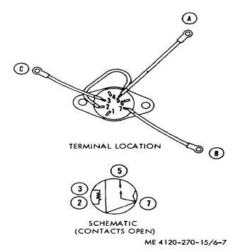
Figure 6-7. Time delay relay test points.
and 4.0 amperes. On model MAC6V60-360-2 the
ammeter should indicate between 4.5 and 3.14 amperes
at full load. When testing the condenser fan motor, the
ammeter should indicate between 18 and 12.6 amperes
at full load for model MAC4V60-360-. On model
MAC6V60-36-2 the ammeter should indicate between
14.5 and 10.2 amperes at full load.
c. Removal. Refer to paragraphs 6-21 and 5-33 and
remove fan motors.
d. Disassembly. Refer to figure 6-8 and 6-9 and
disassemble the fan motors.
e. Testing of Overload Protector. Disconnect the
electrical leads from the overload protector. Test the
protector with a multimeter set on OHMS. If continuity
does not exist, replace the overload protector.
f. Cleaning, Inspection and Repair.
(1) Clean all parts with a cloth dampened in
cleaning solvent.
(2) Inspect the stator housing for cracks,
breaks, or other defects. Replace a damaged or
defective housing.
(3) Inspect bearings for pits, scoring, wear,
and out-of-round. Replace worn or defective bearings.
(4) Inspect the rotor shaft for cracks, wear, and
misalinement. Replace a damaged or defective rotor.
(5) Inspect the rotor for cracks, breaks, and
damaged laminations. Replace the rotor and stator if
they are damaged.
(6) Inspect all threaded parts for damage.
Replace as necessary.
g. Reassembly. Refer to figure 6-8 and 6-9 and
reassemble the fan motors.
h. Installation. Refer to paragraphs 5-21 and 5-33
and install the fan motors.
6-10. Electric Heater Elements
a. General. Two banks of three electrical heaters
each are mounted directly behind the evaporator coil, in
the conditioned air stream, and provide heat on
command from the temperature control thermostat to
maintain the selected ambient temperature. Placing the
selector switch on "LO-HEAT" starts the evaporator
blower and places one bank of heaters in operation on
command from the temperature control thermostat.
Placing the selector switch in "HI-HEAT" activates the
second bank of heaters, which operates continuously in
addition to the controlled bank.
b. Removal. Refer to figure 53 and remove the
heating element assembly from air conditioner.
c. Disassembly. Refer to figure 53. Disconnect
electrical leads from heating elements and remove
elements from support channel assembly.
d. Testing. Using a multimeter set on low OHMS
range, check resistance across each heating element in
turn. Normal reading is 7 ± 4 ohms. Replace heating
element if resistance is not as specified.
e. Reassembly. Refer to figure 5-3. Install elements
in support channel assembly and connect
electrical leads.
f. Installation. Refer to figure 5-3 and install heating
element assembly in air conditioner.
6-11. Heater High Temperature Cutout
a. General. The heater high temperature cutout is a
three-pole,
single-throw,
automatic
reset
thermal
overload and overcurrent protector which prevents the
heaters from operating at discharge temperatures in
excess of 190° ± 40°F regardless of selector switch and
temperature control thermostat settings. Normal heater
operation resumes automatically at 140° ± 40°F
discharge air temperature.
Note. Normally, cutout temperature will be
reached only if evaporator fan motor stops due to
malfunction or if blowers are damaged or seized
.
6-8
|