|
| |
TM 5-4120-270-15
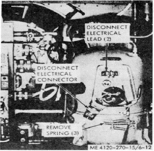
Figure 6-12. Compressor crankcase heater, removal and installation.
Section III. OSCHARGING, PRIESSURE TESTING, EVACUATING AND
RECHARGING THE REFRIGERANT SYSTEM
6-28. Discharging the Refrigerant System
Attach a suitable hose to the suction line access valve
(fig 5-11) and discharge the refrigerant into a safe area.
Warning: Avoid bodily contact with liquid
refrigerant and avoid inhaling refrigerant gas. Be
especially careful that Refrigerant-22 does not come
in contact with the eyes In case of refrigerant leaks,
ventilate the area immediately.
6-29.
Pressure
Testing
and
Evacuating
the
Refrigerant System
Discharge system (para 6-16). Refer to figure 6-13), end
pressure test and evacuate the refrigerant system.
6-30. Charging the Refrigerant System
Refer to figures 6-14 and 6-15; charge the re-
frigerant system.
Note. Capacity of refrigerant sys is 286.9 lb
Refigerant 22 FSN 6830174-9677.
6-16
|