Order this information in Print

Order this information on CD-ROM

Download in PDF Format


Click here to make tpub.com your Home Page

Page Title: Figure 7-6. Liquid quench valve disassembly, exploded view.
Back | Up | Next

Click here for a printable version

Google


Web
www.tpub.com

Home


Information Categories
.... Administration
Advancement
Aerographer
Automotive
Aviation
Combat
Construction
Diving
Draftsman
Engineering
Electronics
Food and Cooking
Math
Medical
Music
Nuclear Fundamentals
Photography
Religion
USMC
   
Products
  Educational CD-ROM's
Printed Manuals
Downloadable Books


TM 5-4120-287-15 1 Coil housing nut 7 Enclosing tube-to-body gasket 2 Coil name plate 8 Plunger and piston assembly 3 Valve name plate 9 Coil assembly 4 Coil housing assembly 10 Coil sleeve (2) 5 Union nut 11 Coilplate 6 Enclosing tube assembly 12 Body and seat assembly Figure 7-5--Continued.
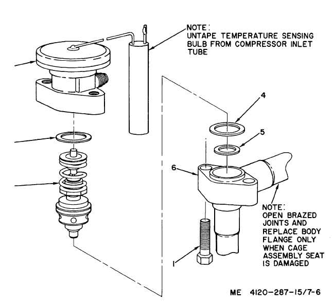
 ___________________________________________________________________________________________________________ 1 Body flange cap screw (2) 3 Cage assembly 5 Seat gasket 2 Power assembly 4 Body flange gasket (2) 6 Body flange Figure 7-6.  Liquid quench valve disassembly, exploded view. 7-13

Privacy Statement - Press Release - Copyright Information. - Contact Us - Support Integrated Publishing

Integrated Publishing, Inc. - A (SDVOSB) Service Disabled Veteran Owned Small Business