|
| |
switch fails to stop the refrigerant compressor.
The relief valve is preset to open at 540
( ± 10%) psig.
b. RemovaL
(1) Discharge the refrigerant system (para
6-3).
(2) Refer to figure 3–4 and remove the lower
front access cover.
(3) Refer to paragraph 3-30 and remove the
junction box.
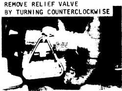
(4) Refer to figure 5--13 and remove the
pressure relief valve.
Figure 5-13. Pressure relief valve, removal and installation.
c. Installation.
(1) Install the pressure relief valve in re-
verse order of removal.
(2) Pressure test, evacuate, and recharge
the refrigerant system ( para 6–5 ).
5-23. Compressor
a. RemovaL
(1) Refer to figure 3–4 and remove the
lower front access cover.
(2) Refer to paragraph 3-30 and remove the
junction box.
(3) Discharge the refrigerant system (para
6-3).
(4) Refer to figure 5-14 and remove the
compressor.
b. Testing.
(1) Check for continuity between pins A and
B, B and C, and C and A of the compressor
electrical receptacle. There should be continuity
in each check.
(2) Check for continuity between pins A, B,
and C, and the compressor housing. There should
be no continuity.
(3) Check for continuity between pins D
and E. Continuity should exist. If compressor in-
herent thermostat is open, allow compressor to
cool and recheck for continuity. If open, replace
compressor.
(4) Check cold resistance tolerances at ter-
minals A and B, B and C, and C and A of com-
pressor (BI) (fig. 1–4). Resistance at each termi-
nal should be 1.3 ( ± 0.5) ohms.
(5) Check amperage draw in phase A, B,
and C at inlet power supply cable, prior to input
power receptacle connector (J11 ) with two speed
fan selector switch in HI-SPEED position. Am-
perage draw at each phase should be 12 (±2)
amperes.
c. Installation.
(1) Install the compressor in reverse order
of rernoval. Refer to paragraph 6-3 for soldering
procedures.
(2) Pressure test, evacuate, and recharge
the refrigerant system (para 6–5).-
(3) install the junction box and lower front
patnel in reverse order of removal.
5-24. Pressure Switch
a. General. The pressure switch is installed to
sense compressor discharge pressure. When the
air conditioner is operated with the fan switch in
the LO-SPEED position, an increase in compres-
sor discharge pressure to 400 ( ± 16) psig will
actuate the normally open pressure switch (S3),
causing the switch to close and the fan speed to
increase to HI-SPEED. When the discharge pres-
sure drops to 350 ( ± 16) psig, the pressure
switch ( S3 ) contacts will return to normally
open and the fan speed will return to LO-SPEED.
b. Testing. Check for continuity between ter-
minals 2 of fuse block (XF2) and X2 of armature
relay (K4). Continuity should not be indicated. If
continuity is indicated, switch is defective and
must be replaced.
c. Removal. Refer to figure 5–15 and remove
the pressure switch.
d. Installation. Installation is the reverse of re-
moval.
5-25. Refrigerant Compressor Mounts
a. RemovaL The compressor mounts are re-
moved during removal of the refrigerant com-
pressor (para 5-23).
b. Installation. Installation is the reverse of
removal.
5-26. Base Assembly and Casing Assembly
a. Removal. Refer to figure 5–16 and remove
the casing assembly from the base assembly.
5-17
|