|
| |
b. Testing.
(1) Disconnect the power source.
(2) Remove the front access panel (para
3-6) and the control box front panel (para 3-25).
(3) Refer to the applicable wiring diagram
(fig. 1-3 or 1-4) and check for continuity be-
tween pins A, B, and C.
Note. With power on, 208 volts at relay, and
phase sequence correct, continuity should exist between
pins 2 and 3 of the relay; if not, replace relay.
c. Removal. Refer to figure 3-11 and remove
the phase sequence relay.
d. Installation. Install the phase sequence
relay, control box front panel, and front access
panel by reversing the order of removal.
3-29. Circuit Breaker
a. General. The circuit breaker protects the
compressor from continuous overload and short
circuits.
b. Testing.
(1) Remove the front access panel (para
3-6) and control box f rent panel (para 3-6).
(2) Refer to figure 3-11 and disconnect the
circuit breaker leads (tag leads for facilitating
installation). Test the circuit breaker for conti-
nuity with a multimeter set on the ohm scale.
Refer to applicable wiring diagram (fig. 1-3 or
1-4) for test points. Auxiliary contacts (pins 3
and 5) are also located on the circuit breaker.
When the circuit is on, continuity should exist
between pins 3 and 5 of the circuit breaker; if
not, replace circuit breaker.
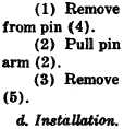
c. Removal. Refer to figure 3-11 and remove
the circuit breaker. Refer to figure 3-12 and dis-
connect the circuit breaker linkage as follows:
the snap ring (1, fig. 3-12)
(4) and spacer (3) from switch
linkage rod (6) and connector
Install the circuit breaker, con-
trol box front panel, and front access panel by
reversing the order of removal.
3-30. Rectifier
a. Testing.
(1) Remove the front access panel (para
3-6) and control box front panel (para 3-26).
(2) Using a multimeter, test the front and
back resistance of the rectifier. A resistance of in-
finity in both directions indicates an open rectifier
that must be replaced.
b. Removal. Refer to figure 3-11 and remove the
rectifier.
c. Installation. Install the rectifier, control box
front panel, and front access panel by reversing
the order of removal.
3-31. Terminal Blocks
a. Removal and Installation.
(1) Remove the front access panel (para
3-6) and the control box front panel (para 3-26).
(2) Refer to figure 3-11 and remove the ter-
minal blocks.
(3) Refer to figure 3-11 and install the ter-
minal blocks.
b. Inspection. Inspect the terminal blocks for
loose terminals and for cracks or breaks. Check
threaded parts for damage or worn threads.
c. Replacement. Replace damaged or defective
parts.
3-32. Compressor and Heater Contractors
a. General. Both contractors are located within
the control box. The compressor contactor starts
the compressor and the heater contractor “ener-
gizes the heaters.
b. Testing.
(1) Remove the front access panel (para
3-6) and the control box front panel (para 3-26).
(2) With power off, coil of contactor for
continutiy “with multimeter set on ohms. Replace
contactor if coil is open or shorted.
(3) When contactor is energized, continuity
should exist across the line and load terminals of
the contactor.
c. Removal. Refer to figure 3-11 and remove
the contractors.
d. Installation. Install the contractors, control
box front panel, and front access panel by revers-
ing the order of removal.
3-33. Outdoor Thermostat
a. General. The outdoor thermostat is mounted
to the rear housing (fig. 1-2) of the air condi-
tioner. It prevents the compressor from being
started when the outside air temperature is below
plus 50° F. when low condensing and suction pres-
sures will hamper system operation.
b. Removal.
(1) Remove the condenser fan guard and
fan (para 3-21).
(2) Tag and disconnect electrical leads con-
necting the outdoor thermostat to the unit.
(3) Remove the two screws securing the
thermostat to the housing.
c. Testing. Test the thermostat for continuity
with a multimeter set on the ohm scale. Refer to
the applicable wiring diagram (fig. 1-3 and 1-4)
3-15
|