|
| |
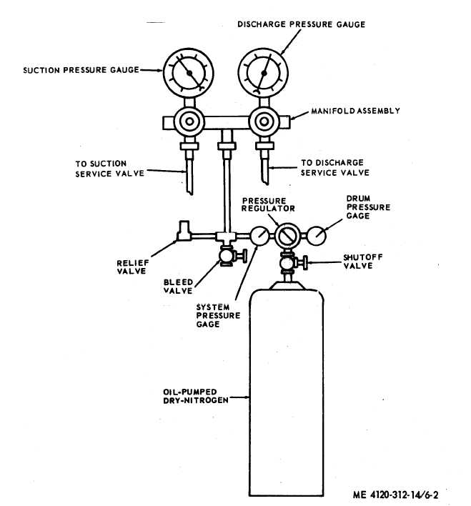
Figure 6-2 Pressure testing (dry nitrogen).
(2) Remove the caps from the service
valves.
(3) Insert the discharge service valve and
suction service valve lines from a suitable pres-
sure manifold (fig. 6-1) through the receptacle
opening and attach loosely to the service valves.
Attach center manifold line to a refrigerant
drum shutoff valve (fig. 6-1). Open shutoff valve
and purge lines.. Tighten connections at both ser-
vice valves.
Note. Set refrigerant drum in an upright position
so that only gaseous refrigerant will enter system. To fa-
cilitate speed of charging, set refrigerant drum in warm
water. Never use a heating torch for this purpose.
(4) Set temperature control above ambient
temperature.
(5) Close discharge service valve.
(6) Install the condenser fan and fan guard
(para 3-21).
(7) Open refrigerant drum shutoff valve.
6-3
|