|
| |
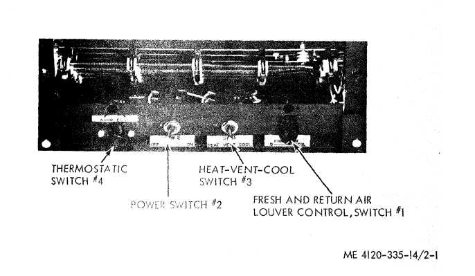
Figure 2-1. Air conditioner, evaporator section, controls and instruments.
2-6. Controls and Instruments
a. Switch # 1. Switch # 1 controls the mixture
of fresh and return air that is supplied to the
evaporator system. It transmits rotary motion of
the knob, via a bell crank, into linear motion which
acting through a wire cable positions the in-
terlocked fresh and return air louvers.
b. Switch # 2. Switch # 2 is the main power
control to the unit. It is a double-throw, tow-
position switch which makes or breaks the flow of
single phase power to the evaporator fan and the
common pole of the heat-vent-coo] switch.
c. Switch # 3. Switch # 3 is a double-throw,
three-position switch serves as the system selector
switch. In the center or “VENT”’ position the
switch makes no contacts and neither heating nor
cooling apparatus operates (but evaporator fan
may run by virtue of feed from switch # 2.) In the
right or “COOL” position, single phase power is fed
through the temperature rise side of the thermostat.
In the “HEAT” position, the switch feeds single
phase power through the temperature drop side of
the thermostat.
d. Switch # 4. Switch # 4 is a thermostatic
control switch which controls both the heating and
cooling elements of the system, maintaining within
the limits of the unit capacity, the temperature at
which it is set. It has a single pole, double-throw
action, switching one way on decrease in tem-
perature, oppositely on increase in temperature.
The temperature sensing bulb is attached to
brackets, located in the return air stream.
2-3
|