 |
|||
|
|
|||
|
Page Title:
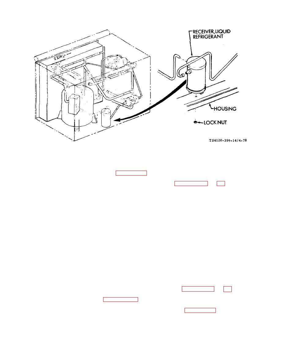
Figure 4-78. Receiver, Liquid Refrigerant |
|
||
| ||||||||||
|
|
 TM 5-4120-359-14
Figure 4-78. Receiver, Liquid Refrigerant
b. Removal
(1) Discharge the refrigerant system per paragraph 4-5.
(2) While purging the system with nitrogen, debraze the tubing. (See paragraphs 4-6 and 4-7.)
(3) Using wrecker or similar hoisting device, lift the condenser section assembly high enough to gain access to
receiver lock nut. Place unit on blocks or boards so that easy access to lock nut can be achieved.
(4) Using socket and ratchet, remove lock nut that attaches the receiver from the recessed hole in the bottom of
condenser housing.
(5) Remove receiver from condenser housing.
c.
Installation
(1) Position receiver in condenser housing so that bottom stud is inserted through mounting hole in bottom
condenser housing channel.
(2) Aline tubing connections.
(3) Using socket and ratchet, secure receiver to bottom condenser housing channel. Lock nut must be inserted
through recessed hole from bottom of condenser housing.
(4) While purging the system with nitrogen, braze the tubing joints. (See paragraphs 4-6 and 4-7.)
(5) Replace the dehydrator. (See paragraph 4-73.)
(6) Leak test all newly connected joints and those in the repair area. (See paragraph 4-8.)
(7) Using wrecker or similar hoisting device, lift the condenser section from supports that were used to gain
access to receiver mounting lock nut.
4-156
|
|
Privacy Statement - Press Release - Copyright Information. - Contact Us |
|
|
Integrated Publishing, Inc. - A (SDVOSB) Service Disabled Veteran Owned Small Business
|

