 |
|||
|
|
|||
|
Page Title:
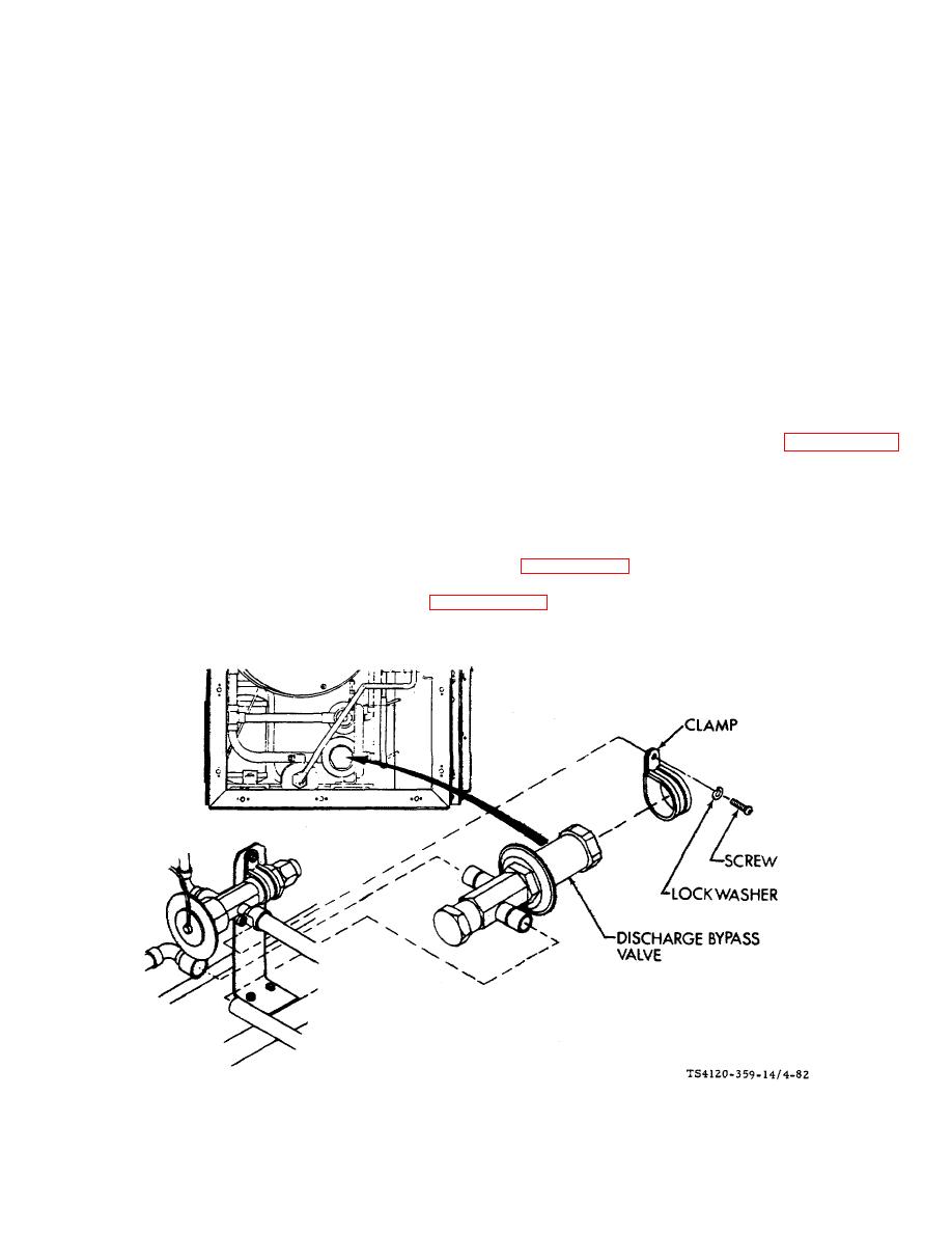
Figure 4-82. Discharge Bypass Valve |
|
||
| ||||||||||
|
|
 TM 5-4120-359-14
(3) Pull module out and to side. Do not disconnect P12 and P13 connectors.
(4) Operate air conditioner in COOL mode with temperature control in maximum WARMER position and pressure
gage connected to LOW SIDE service valve (compressor suction).
(5) Bypass valve should open when LOW SIDE pressure drops to between 52 and 60 psig. ADJUSTMENT is
required it bypass valve does not open when LOW SIDE pressure is 52 to 60 psig.
(6) To adjust, use hand to remove cap (10) covering adjusting screw in bypass valve.
(7) Use 5/16 inch Allen wrench to turn adjusting screw to raise or lower bypass valve opening pressure. Adjust
slowly.
(8) Replace cap.
(9) Turn off air conditioner and disconnect power.
b. Inspect
(1) Inspect for evidence of leaks and external damage. If a leak is indicated, leak test per paragraph 4-8.
Replace valve if damaged.
(2) Check that valve cap is in place.
c.
Removal
(1) Remove air conditioner from shelter if necessary. (See paragraph 3-6.)
(2) Remove right end condenser cover. (See paragraph 3-26.)
(3) Disconnect P12 and P13 connectors and remove condenser section electrical module assembly.
Figure 4-82. Discharge Bypass Valve
4-163
|
|
Privacy Statement - Press Release - Copyright Information. - Contact Us |
|
|
Integrated Publishing, Inc. - A (SDVOSB) Service Disabled Veteran Owned Small Business
|

