 |
|||
|
|
|||
|
Page Title:
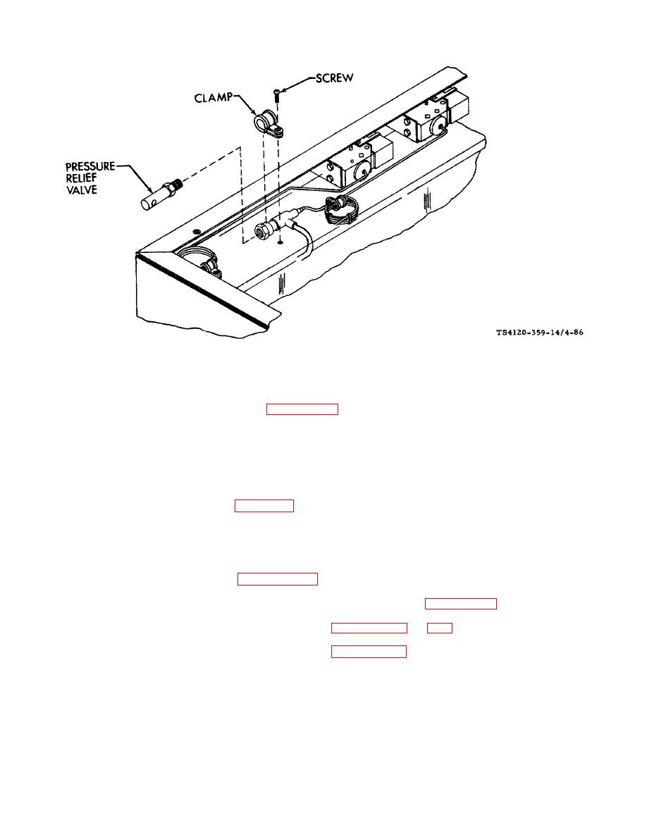
Figure 4-86. Pressure Relief Valve |
|
||
| ||||||||||
|
|
 TM 5-4120-359-14
Figure 4-86. Pressure Relief Valve
b. Removal
(1) Discharge the refrigerant system per paragraph 4-5.
(2) Using screwdriver, remove screw and clamp from top of coil housing.
(3) Use two wrenches. Hold fitting so that it is not twisted, and unscrew pressure relief valve.
c.
Installation
(1) Apply antiseize tape, item 16, Appendix E, to threads of valve.
(2) Use two wrenches. While holding adapter fitting, screw pressure relief valve in place.
(3) Using screwdriver, secure relief valve adapter with screw and clamp.
(4) Replace the dehydrator. (See paragraph 4-73.)
(5) Leak test all newly connected joints and those in the repair area. (See paragraph 4-6.)
(6) Evacuate and charge the refrigerant system. (See paragraphs 4-9 and 4-10.)
Follow-on Procedures: 1. Install top condenser cover. (See paragraph 3-25.)
2. Connect power.
4-170
|
|
Privacy Statement - Press Release - Copyright Information. - Contact Us |
|
|
Integrated Publishing, Inc. - A (SDVOSB) Service Disabled Veteran Owned Small Business
|

