 |
|||
|
|
|||
|
Page Title:
Figure 4-105. Diode with Terminal |
|
||
| ||||||||||
|
|
 TM 5-4120-359-14
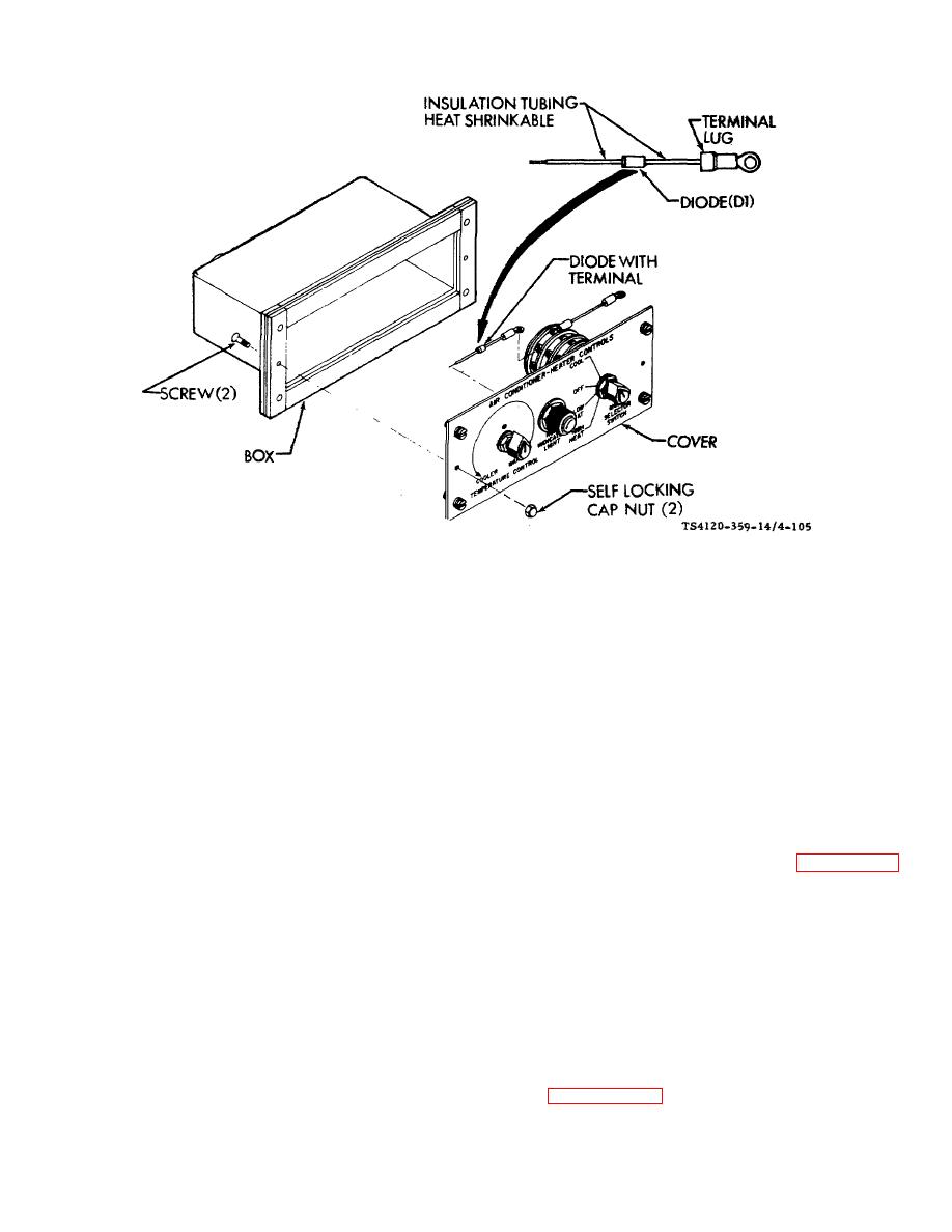
Figure 4-105. Diode with Terminal
(3) Check for loose solder connection or terminal lug.
(4) Check that diode is connected between switch terminal S1-41 and light terminal XDS1-2.
(5) Using multimeter, check diode. Diode (D1) ratio of backward resistance to forward resistance should be not
less than 100 to 1.
b. Removal
(1) Disconnect terminal lug at rotary switch.
(2) Unsolder lead at light.
(3) Remove diode and terminal.
c. Repair. Repair is limited to replacement of terminal lug and heat shrinkable insulation tubing. See paragraph 4-3
for general wire repair instructions.
d. Installation
(1) Solder lead to terminal XDS1-2 on light.
(2) Connect terminal lug to terminal S1-41 on rotary switch.
(3) Slip box and cover together and aline solder.
(4) Using screwdriver and wrench, secure box to cover with two screws and self locking cap nut.
Follow-on Procedures: Install remote control assembly in shelter. (See paragraph 4-99.)
4-208
|
|
Privacy Statement - Press Release - Copyright Information. - Contact Us |
|
|
Integrated Publishing, Inc. - A (SDVOSB) Service Disabled Veteran Owned Small Business
|

