 |
|||
|
|
|||
|
Page Title:
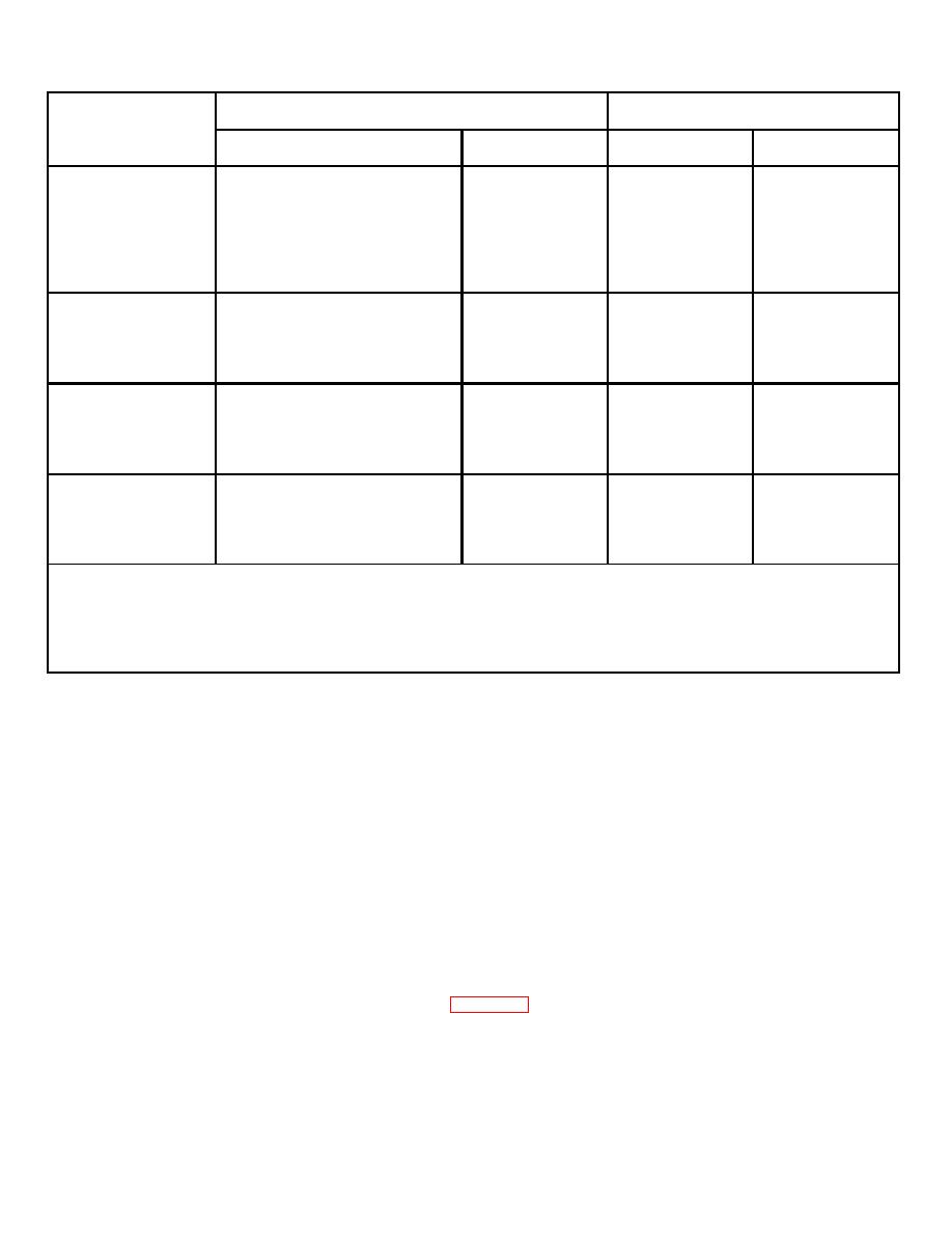
ROTARY, MODE SELECTOR, SWITCH (S1) AND KNOB (Continued) |
|
||
| ||||||||||
|
|
 TM 5-4120-359-14
Resistance Reading (Ohms)
J14 CONNECTOR
Temperature Control Set To
Resistance less than
Maximum
Maximum
Mode
2 ohms (Pins)
Pins
WARMER
COOLER
COOL
A to B
C to H
*
*
C to N
N to D
N to H
*
*
M to P
J to L
1000
1000
J to K
1000
0
K to L
0
1000
OFF
C to N
C to H
*
*
N to H
*
*
J to L
1000
1000
J to K
1000
0
K to L
100
1000
LOW
A to B
C to H
*
*
HEAT
C to N
N to H
*
*
M to G
J to L
1000
1000
J to K
1000
0
K to L
0
1000
HIGH
A to B
C to H
*
*
HEAT
C to N
N to H
*
*
C to F
J to L
1000
1000
M to G
J to K
1000
0
K to L
0
1000
*
Resistance values on multimeter will vary with internal resistance of meter scale used in addition to the
forward and backward resistance of diode (D1). Backward to forward resistance ratio of diode (D1) should
be approximately 100 to 1.
For example: Resistance from H to C may read 8 ohms and when leads are reversed, read approximately
800 ohms.
c.
Removal
(1) Using allen wrench, loosen setscrew in knob.
(2) Remove knob.
(3) Tag and disconnect leads.
(4) Using wrench, remove nut, lock washer, and locking ring from rotary switch.
(5) Remove rotary switch.
d. Installation
(1) Position rotary switch with locking ring, lock washer, and nut. Positioning tab on locking ring must fit into hole
in cover.
(2) See tags, wire markings, and wiring diagram (figure 4-3), and reconnect leads.
4-210
|
|
Privacy Statement - Press Release - Copyright Information. - Contact Us |
|
|
Integrated Publishing, Inc. - A (SDVOSB) Service Disabled Veteran Owned Small Business
|

