|
| |
TM 5-4120-361-14
Section VII.
MAINTENANCE OF AIR CONDITIONER
4-20.
Electrical System.
This section describes the testing,
removal, and installation of the elec-
trical system compnents which are the
responsibility of organizational main-
tenance.
Refer to the schematic (figure
1-4) for cmponent nomenclature and as a
guide for troubleshooting. use the wir-
ing diagram (figure 1-5) to check the
exact connections of wiring.
4-21.
Evaporator Fan and Motor Assem-
bly.
a.
General.
The evaprator fan mo-
tor is a multispeed motor.
The 400 Hz
motor operates at 3750 RPM in high speed
and 1800 RPM in low speed.
The 60 Hz
motor operates at 3450 RPM in high speed
and 1725 RPM in low speed.
The motor
contains separate windings for high or
low speed operation and each winding is
thermally protected.
Motor speed is
manually controlled by the evaporator
fan speed switch.
b.
Controls.
Before removing the
evaporator fan and motor assembly, test
the mode selector switch, evaporator fan
speed switch, and control circuit break-
er (para 4-26) and evaporator fan motor
low/high speed switch (para 4-27) which
control operation of the motor. If
electrical control components or wiring
that supply power to the motor are not
defective and the motor does not oper-
ate, proceed as follows:
c.
Removal.
(1) Refer to figure 4-1 and remove
the evaporator air inlet louver.
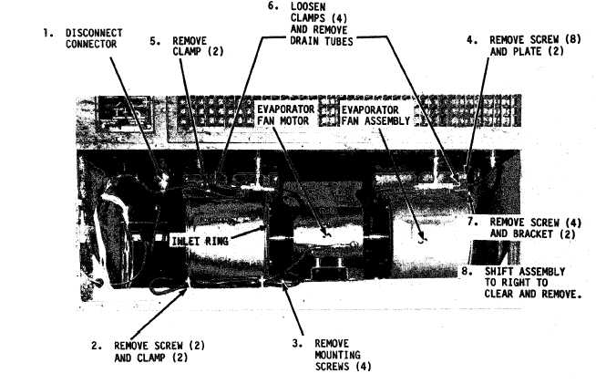
(2) Refer to fiqure 4-7 and remove
the evaporator fan and motor assembly.
(3) Refer to figure 4-8 and dis-
assemble the fan and motor assembly.
Figure 4-7.
Evaporator fan and motor assembly, removal and installation
4-15
|