 |
|||
|
|
|||
|
|
|||
| ||||||||||
|
|
 TM 5-4120-364-13
(b)
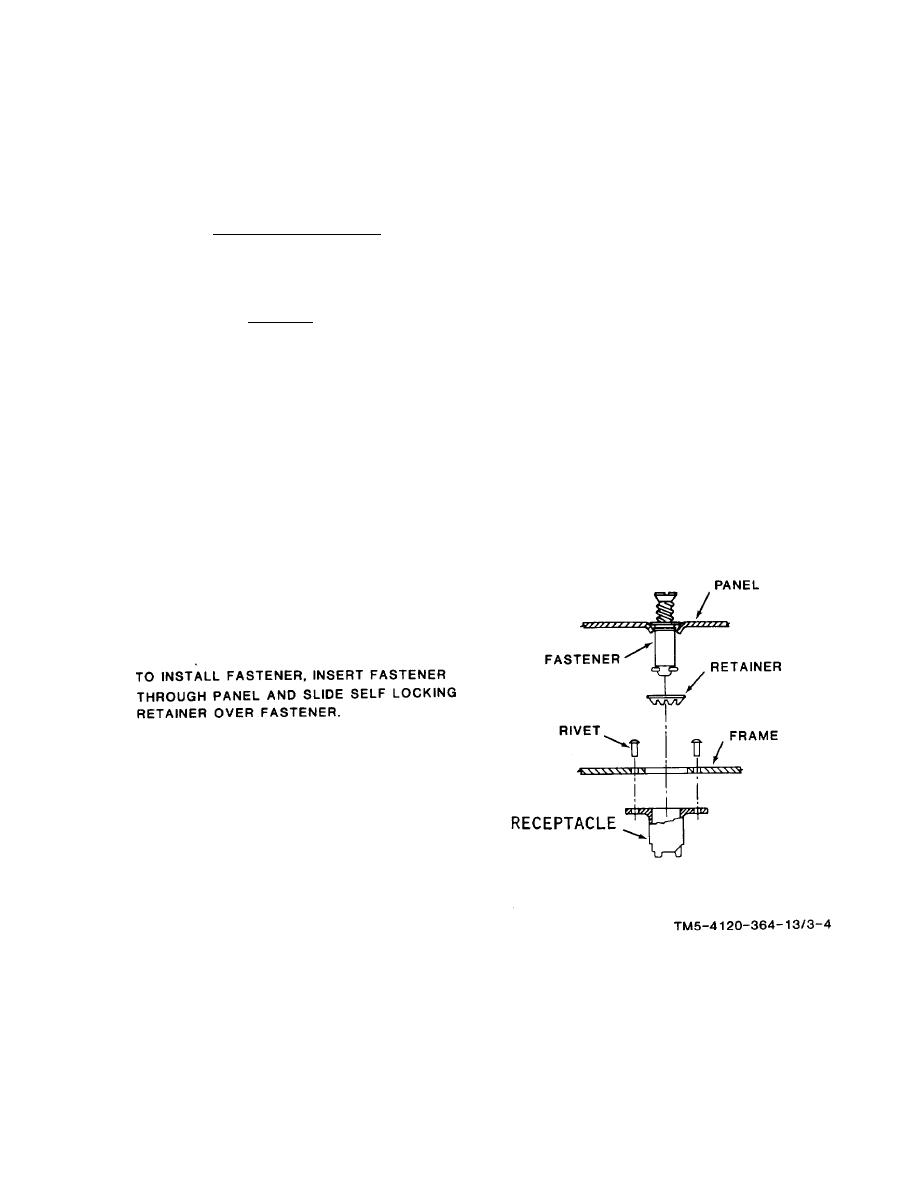
Replace defective fasteners. (See figure 3-4).
(c)
Replace defective gaskets. New gaskets are installed by removing
t h e strip from the
gasket adhesive backing and pressing the gasket in place.
(d)
Glue loose or new insulation to the panels with adhesive.
(e)
Install panels and secure by turning the fasteners one-quarter
t u r n clockwise.
b . Fan Housings and Fans. T h e evaporator fan assembly consists of a dual
s q u i r r e l cage type fan and housings powered by a 1/3 HP, 120 volt, single phase 50/
6 0 Hz electric rotor. The motor is equipped with permanently lubricated ball bearings
and an overload protector which will reset itself automatically after cooling.
(1) R e m o v a l .
( a ) Refer to figure 3-3 and remove front, rear and end panels from
t h e evaporator fan section by turning fasteners (9) one-quarter turn counterclock-
wise.
( b ) Remove screws (18, figure 3-5), washers (19) and ring (20) from
housing (26).
Figure 3-4. Panel fastener and receptacle installation
3-9
|
|
Privacy Statement - Press Release - Copyright Information. - Contact Us |
