|
| |
TM5-4120-375-14
POWER WIRING HARNESS (CONT.)
LOCATION/ITEM
ACTION
REMARKS
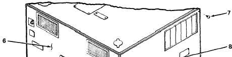
INSTALLATION
10. Right Side Panel
a.
Align holes in right side panel (8) with holes in
frame.
b.
Secure right side panel with thirty-one
screws (7).
11. Front Panel
a
Align holes in front panel (6) with holes in
frame.
b.
Secure front panel with thirty-four
screws (4) and two screws (5).
12. Control Box
a.
Connect electrical connector (P-6) to control
box .
b.
Align holes in control box (3) with holes in
front panel and frame.
4-104
c .
Secure control box with four screws (2) and
four screws (1).
|