Order this information in Print

Order this information on CD-ROM

Download in PDF Format


Click here to make tpub.com your Home Page

Page Title: INSTALLATION
Back | Up | Next

Click here for a printable version

Google


Web
www.tpub.com

Home


Information Categories
.... Administration
Advancement
Aerographer
Automotive
Aviation
Combat
Construction
Diving
Draftsman
Engineering
Electronics
Food and Cooking
Math
Medical
Music
Nuclear Fundamentals
Photography
Religion
USMC
   
Products
  Educational CD-ROM's
Printed Manuals
Downloadable Books


TM5-4120-375-14 THERMAL  EXPANSION  VALVE  (CONT.) LOCATION/ITEM ACTION REMARKS INSTALLATION 5. Thermal  Expansion  Valve g. h. Position bulb in same i. j  . k. 
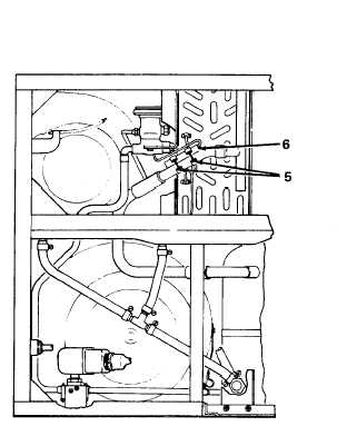
Secure sensing bulb to suction line with two band clamps (5). Wrap the sensing bulb (6) with insulating tape (Item 6, table D-1) being careful to avoid kinking tube. NOTE position as it was removed. Carefully install the sensing bulb to its position on the suction line. Clamp into position on the suction line. Cover suction line, sensing bulb and clamps  with  insulating  material. Carefully  form  the  capillary  tube  along  adjacent piping. Leak check, evacuate and charge system in accordance with paragraphs 5-16 thru 5-18. 5-58

Privacy Statement - Press Release - Copyright Information. - Contact Us - Support Integrated Publishing

Integrated Publishing, Inc. - A (SDVOSB) Service Disabled Veteran Owned Small Business