|
| |
TM5-4120-376-14
4-24. HEATER, TRANSFORMER, RECTIFIER AND RELATED PARTS/Inspect, Test, Replace
(Cont)
LOCATION/ITEM
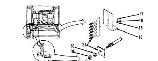
Installation:
1. Attach heater element wires to appropriate terminal on terminal board in accordance with
Appendix E and remove tags.
2. Align heater element (21) with hole in housing and secure with one lock washer (20) and
one nut (19).
3. Slide heater element mounting bracket (18) on to heater elements.
4. Align heater element mounting bracket with holes in housing and secure with two flat
washers (15) two lock washers (16) and two screws (17).
5. Install junction box in accordance with paragraph 4-22, page 4-118.
6. Slide thermostat sensor bulb (10) thru junction box (14) to left evaporator fan housing (11).
7. Secure thermostat sensor bulb to left evaporator fan housing with two clamps (9) two lock
washers (8) and two screws (7).
8. Slide control module into junction box.
9. Secure control module to junction box with knob (12).
10. Align front louver (evaporator inlet) (6) with housing and secure with ten screws (4) and
ten lock washers (5).
4-139
|