|
| |
4-33.
TM 5-4120-377-14
l Place flat washer and sealing nut on to end of reset cable and tighten finger tight.
l Using wrench, tighten nut on back side of box.
l Pull shaft out and place small nut on end of shaft.
l Screw knob onto end of shaft.
l Tighten small nut.
(4) Slip ground stud thru panel and secure with two nuts, two flat washers, and one lock washer.
(5) Using screwdriver, secure back panel with twenty-one flat head screws and twenty-four pan head screws
and flat washers.
(6) Using screwdriver, secure refrigerant sight glass bracket with two screws, packing with retainers, and
lock washers.
Follow-on procedures: 1. Install top panel. (See para 4-28.)
2. Install fresh air inlet screen. (See para 4-27.)
3. Install condenser (fan) guard. (See para 4-25.)
4. Install access (service valve) cover. (See para 4-20.)
5. Install CBR duct cover. (See para 4-19.)
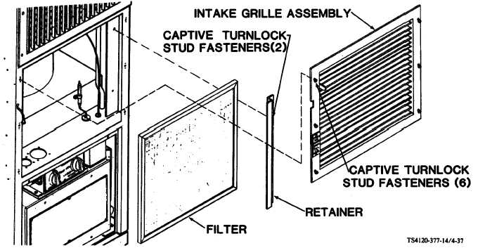
Figure 4-37. Conditioned Air Filter
a. Removal
(1) Using screwdriver, loosen six captive turnlock stud fasteners in intake grille assembly.
(2) Remove grille.
4-67
|