|
| |
PARA 4-9.
TM 5-4120-377-14
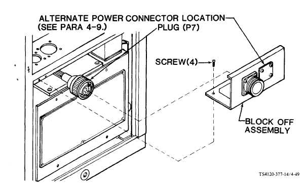
Figure 4-49. Block Off Assembly Installed
(3) Pull connector from block off.
(4) If alternate location for power connector was used, remove the connector.
(5) Using screwdriver, remove four screws from lower flanges.
(6) Remove block off assembly.
b. Inspection
(1) Check block off for missing parts, loose hardware, and cracks or dents that would create a hazard or
interfere with operation.
NOTE
If alternate power and control connector locations
cover plates should be installed on block off.
(2) Replace all missing or damaged parts.
in conditioned air intake are used, both
c. Repair. Repairs are limited to replacement of missing or damaged parts.
d. Installation. (See installation instructions paragraph 4-7.)
(1) If applicable, connect the P7 plug and harness.
(2) If applicable install power connector.
(3) Using screwdriver, secure block off to air conditioner with four screws.
(4) Install lower
Follow-on procedure:
4-86
front panel. (See para 4-29.)
Connect power.
|