|
| |
TM5-4120-377-14
(9) Evacuate and charge the refrigerant system. (See para 5-10 and 5-11.)
Follow-on procedure:
Install junction box. (See para 4-46.)
5-20. COMPRESSOR (B1)
Preliminary procedures: 1. Remove
2. Remove
junction box. (See para 4-46.)
side access plate. (See para 4-22.)
The compressor and motor assembly are hermetically sealed in a metal canister and are not repairable. The
following items may be replaced without opening the refrigerant pressure system:
l Connector (J4)
l H e a t er
l Heater thermostat
a. Inspection/Test
(1) Be sure power has been disconnect from air conditioner.
(2) Electrically test the heater element, heater thermostat, wiring harness, and motor as follows.
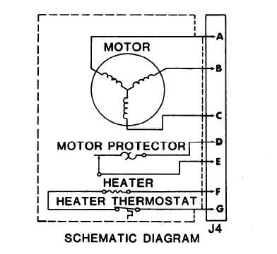
(3) Disconnect wiring harness at connectors P4 and J4 (located on the compressor junction box).
Figure 5-17. Compressor Schematic
Do not touch heating element.
TS4120-377-14/5-17
5-35
|