|
| |
TM5-4120-377-14
6-4. LIFTING HANDLES
Preliminary procedures:
1. Remove junction box. (See para 4-46.)
2. Remove liquid quench expansion valve. (Only if left handle and enclosure are to
be removed.) (See para 5-19.)
a. Removal
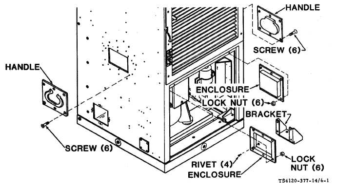
(1) Using screwdriver and wrench, remove six screws and nuts from each handle and enclosure.
Figure 6.1. Lifting Handles
Remove handle(s) and enclosure(s).
If bracket on Ieft enclosure is to be replaced:
l Use a drill slightly smaller than the diameter of the rivet body to drill out the four rivets.
l Secure the new bracket with four rivets.
b. Installation
(1) Place the handle(s) on the outside and the enclosure(s) on the inside of the casing side panel(s).
(2) Aline mounting holes.
(3) Using screwdriver and wrench, secure the handle(s) and enclosure(s) with six screws and lock nuts
(each handle).
Follow-on procedure:
Install liquid quench expansion valve. (Only if left handle and enclosure were
removed.) (See para 5-24.)
6-3/6-4 blank
|