 |
|||
|
|
|||
|
Page Title:
Installation Instructions (cont) |
|
||
| ||||||||||
|
|
 TM 5-4120-393-14
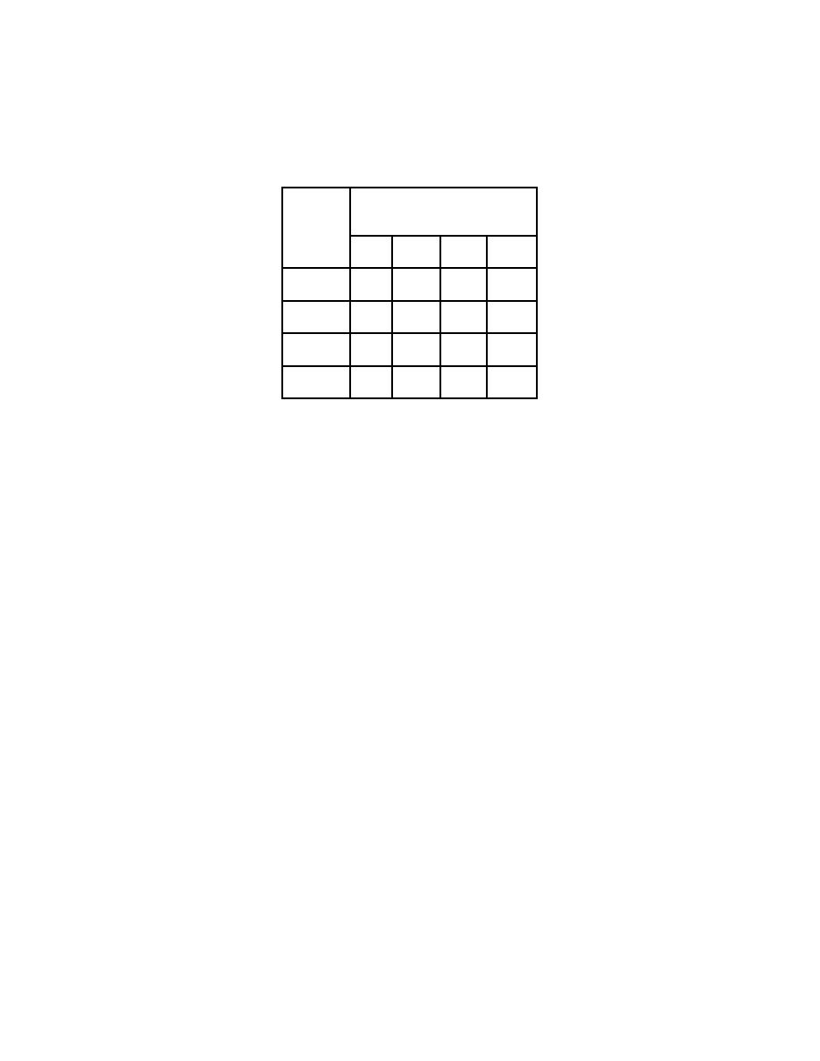
(4) With zero voltage on pin D of P1 connector, check voltages between remaining pins as shown on following
chart.
P1 CONNECTOR
Measure
To Pin
From
Pin
A
B
C
D
A
N/A
208
208
120
B
208
N/A
208
120
C
208
208
N/A
120
D
120
120
120
N/A
Voltages should be approximately as shown. If voltages are not within ten volts of those
indicated on chart, disconnect power. Locate and correct problem.
CAUTION
Check that mode selector switch is OFF.
(5) After proper voltages are indicated on all pins of connector P1, turn power off at power source and connect
P1 to connector J1 on air conditioner. Turn power back on at source after J1 has been connected to the ACU.
NOTE
The following steps require two people. One must be at control panel. The other
must be in position at rear of air conditioner to see condenser fan rotation.
(Condenser fans can be seen through condenser air outlet grilles.) Should
dampers be closed, remove lower front panel to observe fans.
(6) The person at control panel should turn mode selector switch to COOL and immediately back to OFF.
4-17
|
|
Privacy Statement - Press Release - Copyright Information. - Contact Us |
|
|
Integrated Publishing, Inc. - A (SDVOSB) Service Disabled Veteran Owned Small Business
|

