 |
|||
|
|
|||
|
|
|||
| ||||||||||
|
|
 TM 5-4120-393-14
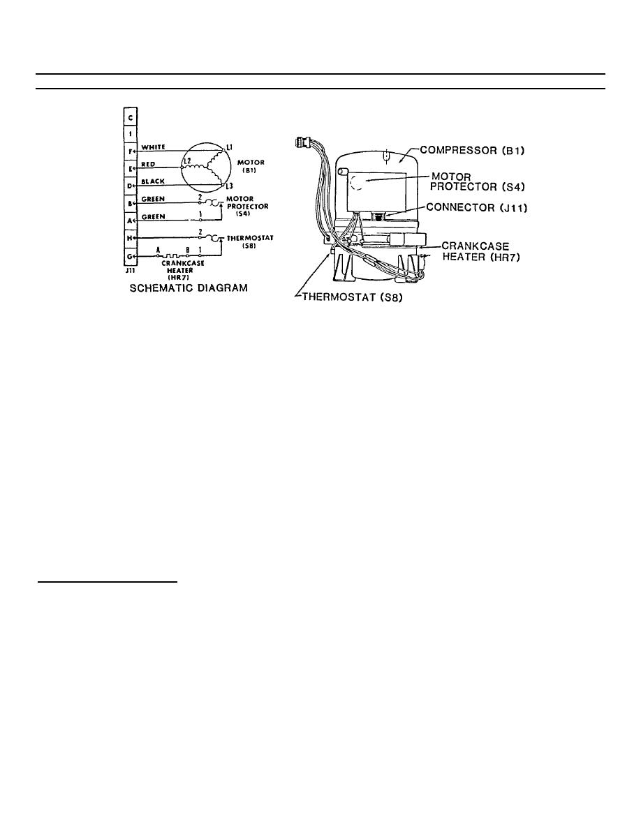
5-28. Compressor (B1) (cont)
b.
Remove wing nut from compressor junction box cover and pull junction box cover from compressor.
c.
Check that all wire connections are secure and in good condition.
d.
Using multimeter, check continuity between connector (J11) contacts D to E, D to F, and E to F. Continuity
should be indicated. If continuity is not indicated, check that wires are properly connected. If wires are properly
connected and continuity is still not indicated, replace compressor.
e.
Check continuity between J11 contacts A and B. If there is no continuity and wires are properly connected, the
motor protector (internal thermostat) is open. Replace the compressor.
f.
Check continuity between J11 contacts A, B, D, E, and F and compressor canister. If wires are properly
connected and there is continuity indicated, there is an internal short. Replace the compressor.
g.
Check continuity between J11 contacts G and H. If there is continuity between these pins, both the heater
element and thermostat are all right. If there is no continuity between the pins, bare the splice between the heater
lead and thermostat lead, and separately check for continuity between pin G and the splice, but not between pin
H and the splice, the heater element is all right and the thermostat is bad. If there is continuity between pin H and
the splice but not between pin G and the splice, the thermostat is all right and the heater element is bad. If there
is no continuity between either pin and the splice, both the element and the thermostat are bad.
REPLACE CONNECTOR J11
NOTE
Refrigerant system discharge is not required.
1.
Check to see that the power has been disconnected at the power source, and covers have been removed during
access and testing.
2.
Remove the retaining hardware from the connector. Pull the connector out of the box to gain access to the solder
connections.
5-68
|
|
Privacy Statement - Press Release - Copyright Information. - Contact Us |
|
|
Integrated Publishing, Inc. - A (SDVOSB) Service Disabled Veteran Owned Small Business
|

