|
| |
TM 55-8145-221-14&P
Change 1
0021 00-6
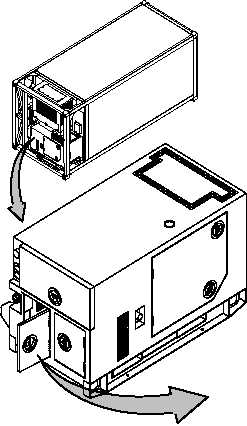
GENERATOR SET REPLACEMENT – Continued
0021 00
INSTALLATION – Continued.
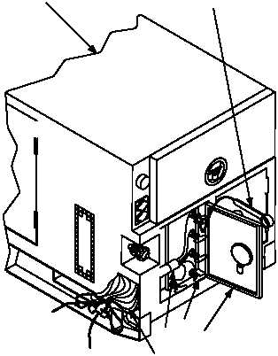
4. Connect power cable (7, Figure 3) to generator set (1) as follows:
a. Open terminal door (8). Insert power cable (7) through weather boot (9) into terminal compartment.
b. Remove fastener tool (10). Raise retention clips (11) on each terminal.
c. Connect black wire to terminal L1.
d. Connect white wire to terminal L2.
e. Connect red wire to terminal L3.
f.
Connect green wire to terminal L0.
g. Use fastener tool (10) to tighten nuts on each terminal.
h. Clip retention clip (11) over each terminal and return fastener tool (10) to storage position.
i.
Close terminal box door. (8). Secure weather boot (9) around cable (7).
Figure 3. Generator Set Installation (Sheet 2 of 4)
1
10
VIEW ROTATED
90° CCW
FOR CLARITY
VIEW ROTATED
90° CW
FOR CLARITY
8
9
7 11
|