|
| |
TM 55-8145-221-14&P
OPERATION UNDER USUAL CONDITIONS – Continued
0006 00
OPERATING PROCEDURES – Continued.
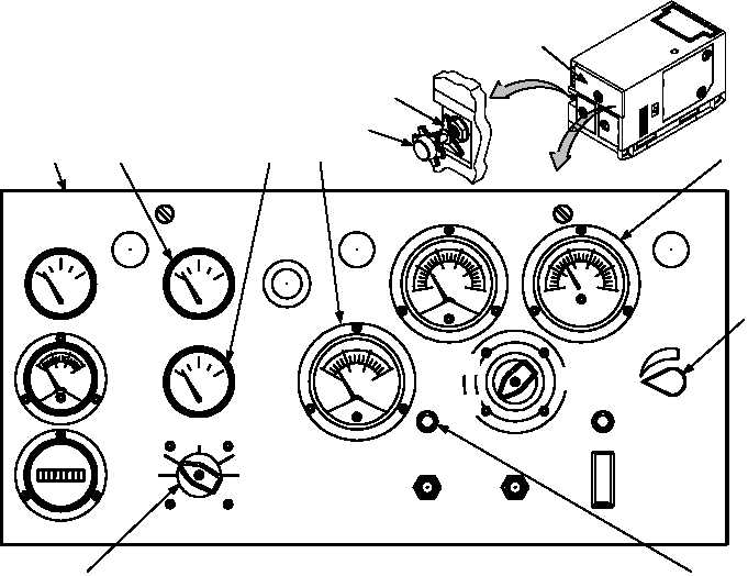
GENERATOR STARTING PROCEDURE (Figure 7).
1. Rotate MASTER SWITCH (1) to START position.
2. Hold MASTER SWITCH (1) in START position until OIL PRESSURE GAUGE (2) reaches at least 25 psi (172 kPa),
AC VOLT METER (3) has increased to its approximate rated value, and engine has reached stable operating speed.
3. Release MASTER SWITCH (1) to PRIME AND RUN position. If operating with an auxiliary fuel source, rotate
MASTER SWITCH to PRIME AND RUN AUX FUEL position.
4. Check COOLANT TEMP (4) [170-200F (77-93C)] and OIL PRESSURE GAUGE (2) [25-60 psi (172-414kPa]
indicator readings.
5. Adjust VOLTAGE potentiometer (5) until AC voltmeter (3) indicates 208VAC.
6. Loosen frequency control locknut (6) and adjust the frequency adjust control knob (7) until frequency gauge (8) indicates
60HZ. Tighten locknut (6).
7. Place AC CIRCUIT INTERRUPT switch (9) to CLOSED position.
8. Ensure frequency and voltage are still at required values. Adjust if necessary.
9. Close generator control panel door (10).
3
PRESS
TO RESET
FUEL LEVEL
BATTERY CHARGE
E
F
1/2
FUEL
COOLANT TEMP
OIL PRESSURE
MASTER SWITCH
PRIME & RUN
AUX FUEL
START
OFF
PREHEAT
ENGINE
TOTAL HOURS
EMERGENCY
STOP
PUSH
TO STOP
OFF
OPEN
BATTLE SHORT
VOLTAGE
POWER
ON
OFF
ON
CLOSED
PERCENT
RATED
CURRENT
AC
VOLTS
HOBBS
QUARTZ
PRIME
& RUN
AC CIRCUIT
INTERRUPTER
PANEL
LIGHTS
100
140
180
240
0
80
40
PRESSURE
AMPERS
D.C.
0
-10
+10
+20
CHARGE
DISCHARGE
55
HERTZ
60
65
70
0
25
50
75
100
125
133
60 HERTZ
100
140
180
220
260
300
3
AM-VM
VOLTS
PHASE
L3-L1
3
L3-L0
1
7
6
2
4
8
10
3
5
1
CONTROL PANEL SHOWN OPEN
9
Figure 7. Generator Control Panel (Starting Procedure)
Change 1
0006 00-10
|