 |
|||
|
|
|||
|
Page Title:
Figure 3-22. Tube section being installed (single splice). |
|
||
| ||||||||||
|
|
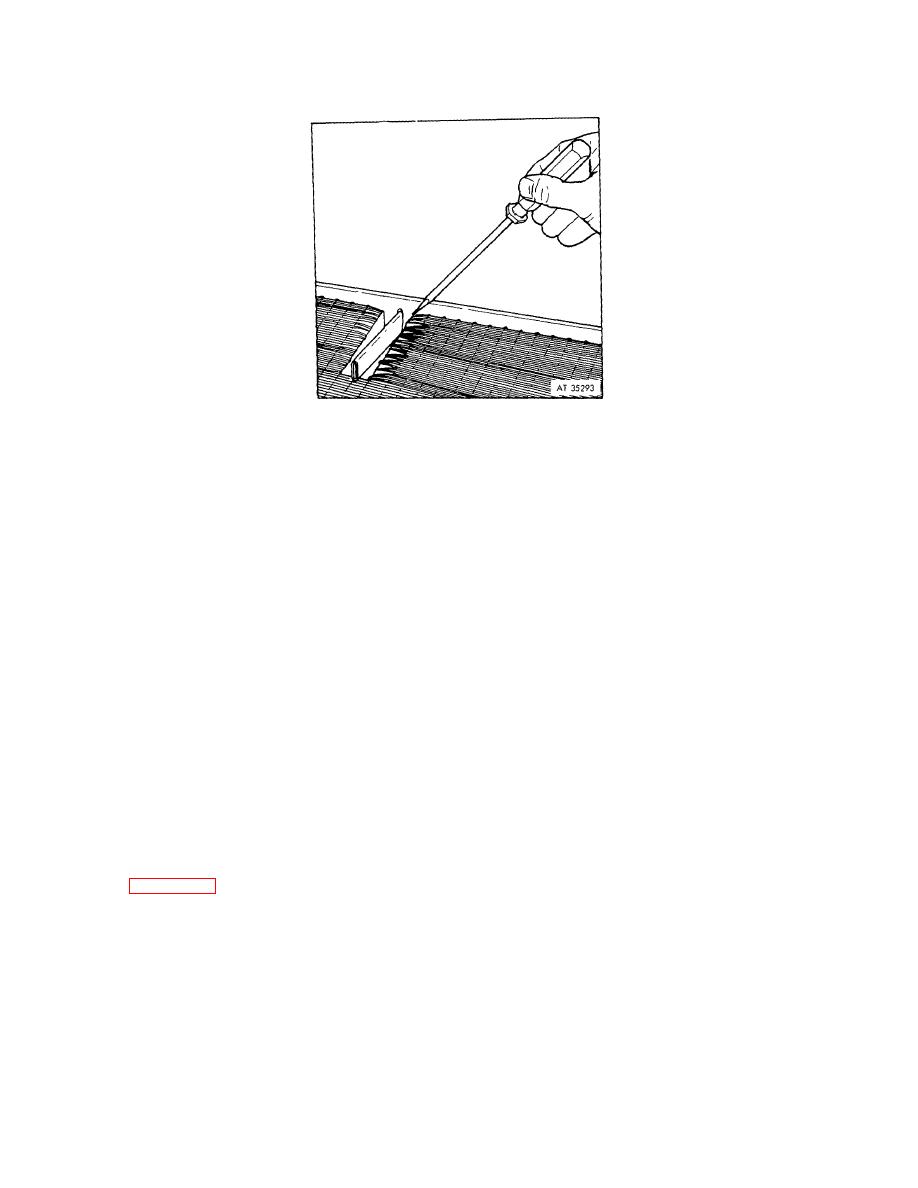 (5) Flare the angle-cut end of the tube to be spliced. Tin ends of tubes that have been cut.
(6) Fit new section into the header hole and lower other end into flared end of tube being spliced. Fig-ure 3-22
shows tube being installed.
Figure 3-22. Tube section being installed (single splice).
(7) Form flared end around new section. Apply flux and solder angle-cut end in usual manner as previously
described. Be careful solder does not flow inside tube.
(8) Solder other end of tube in header.
(9) Straighten fins with duck bill pliers. Bond fins to tube using small amount of solder.
(10) Leak test with the required air pressure.
e. Double Splice Repair of Continuous Fin Types
(1) Heat a small section of fin, grip with needle nose pliers and twist out section. Remove evenly to provide a
straight slot on each side of the repair area.
NOTE
Tear and remove only the number of fins that are required to make the repair.
(2) Cut the damaged section of the tube at both ends with tin snips. The cut must be at an oblique angle to
increase bonding area. An angle of 45 is recommended.
(3) Cut a new section from tube stock approximately l/2 Inch longer than the removed section. Cut new section
at a square 90 angle.
NOTE
The tube stock may be one size smaller than removed section for ease of fitting.
(4) Open collapsed ends of tube with needle nose pliers.
(5) Flare both ends of tube to be spliced so new section will fit inside.
(6) Tin all ends of tubes that have been cut.
(7) Fit new tube section inside flared ends.
(8) Form flared ends around new section, flux and solder spliced section. Be careful that solder does not flow
inside tube. Figure 3-23 illustrates new tube section being installed.
(9) Leak test with the required air pressure.
|
|
Privacy Statement - Press Release - Copyright Information. - Contact Us |
