|
| |
TM 9-4110-257-14
5-26. STOP VALVE ( DEFROST LINE ) REPLACEMENT.
This task covers:
a.
Testing
b.
Removal
c.
Installation
INITIAL SETUP:
Materials/Parts:
Equipment Conditions:
Self Locking Nuts (2)
Refrigeration system discharged (para 5-7) and purged
12, Appendix G
(para 5-8).
Both front bottom doors open.
a.
Removal.
(1)
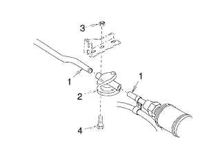
Purge (para 5-8) and de-braze (para 5-9) two fittings (1) from stop valve (2).
(2)
Remove two self locking nuts (3), bolts (4), and stop valve (2). Discard self locking nuts.
Figure 5-22. Stop Valve
b.
Installation.
(1) Install stop valve (2), two bolts (4) and new self locking nuts (3).
(2) Purge (para 5-8) and braze (para 5-9) two fittings (1) onto stop valve (2).
NOTE
FOLLOW-ON MAINTENANCE: Close both front bottom doors. Replace dehydrator (para 5-14).
Leak check (para 5-10), evacuate (para 5-11), and charge (para 5-12) the refrigeration system.
5-52
|