|
| |
TM 9-4120-367-14
TM 07592B-14/1
Location/Item
Testing
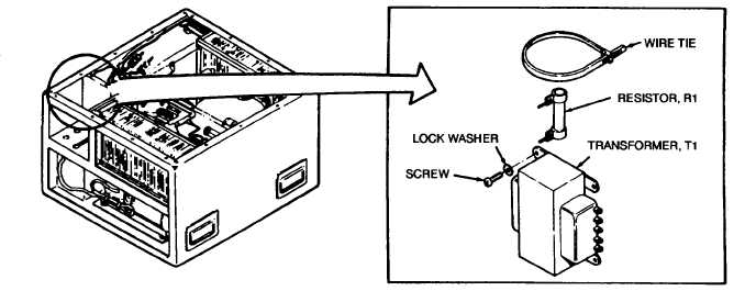
Installation
Figure 5-5. Transformer T1
Action
a.
b.
a.
b.
Tag and disconnect leads and check for continu-
ity across the primary winding and then across
the secondary winding. If either winding is open,
replace the transformer.
Check for shorts between one terminal and trans-
former case and also between one primary termi-
al and one secondary terminal using multimeter
on high ohms setting. Replace transformer if a
short is indicated.
Slip heat-shrink tubing over the leads.
Solder leads to transformer.
Terminal Connection
(Models F18H, F18H-3 & F18H-4)
Resistor R1
1
X35A20N
2
X37A20
3
X38A20
4
Remarks
5-15
5.7. TRANSFORMER T1. - Continued
Wire No.
Terminal No.
|