|
| |
TM 9-4120-367-14
TM 07592B-14/1
Location/Item
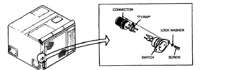
Figure 5-27. Fan Switch
Action
a.
b.
c.
d.
e.
f.
g.
h.
i.
Slip heat-shrink tubing over the two leads.
Wire
Plug
Terminal No.
V9B20
2
A
V5D20
1
B
Pull tubing over solder joint.
Hot air dry tubing.
Push switch into frame.
Secure with two screws and washers.
Connect plug P7.
Secure wires to cable with “ty-rap.”
Replace top cover.
Connect power supply.
Remarks
5.27 CONDENSER FAN SWITCH S7 - Continued
Installation
No.
Switch
Terminal
5-82
|