|
| |
ARMY TM 9-4120-381-14
NAVY EE-000-CA-MMA-010/7053-AC
AIR FORCE TO 35E9-136-31
1-6.
DESTRUCTION OF ARMY MATERIEL TO PREVENT ENEMY USE. Command decisions, according to tactical
situation, will determine when destruction of the air conditioning unit will be accomplished. A destruction plan will be
prepared by the user organization unless one has been prepared by higher authority. For general destruction procedures
for this equipment, refer to TM 750-244-3, Procedures for Destruction of Equipment to Prevent Enemy Use.
1-7.
PREPARATION FOR STORAGE OR SHIPMENT. Contact unit maintenance for air conditioning unit preparation
for storage or shipment. See para 4-93 for instructions.
Section II. EQUIPMENT DESCRIPTION
1-6.
EQUIPMENT CHARACTERISTICS, CAPABILITIES, AND FEATURES. The MOAC 640 air conditioning unit is
designed to ventilate, cool or heat, and to filter and circulate air in enclosures.
a.
Provides a maximum of 50,000 BTU/HR of cooling and 34,150 BTU/HR of heating.
b.
Has one stage of heat.
c.
Provides a source of filtered outside (fresh) ventilation air.
d.
Is self contained in single cabinet that is suited for van, shelter or other enclosed areas.
e.
Operates in environmental conditions from arctic to tropic.
f.
Is EMI/RFI shielded; compatible with electronic equipment.
g.
Capable of control and interface for operation with remote control panel.
h.
Capable of supply or return air temperature control.
i.
Automatic unit shut down in fault condition, with manual reset.
j.
Provides for local and remote fault indications.
k.
The hot gas bypass system permits continuous running of the compressor.
1-9.
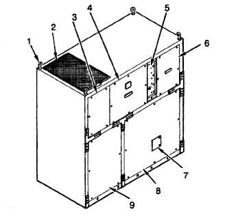
LOCATION AND DESCRIPTION OF MAJOR COMPONENTS.
a.
External Components (Front View).
Figure 1-1. External Components (Front and Top Views).
1-2
|