|
| |
ARMY TM 9-4120-381-14
NAVY EE-000-CA-MMA-010/7053-AC
AIR FORCE TO 35E9-136-31
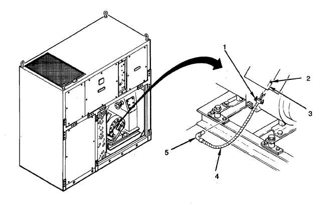
Figure 4-81. Compressor Crankcase Heater
INSTALLATION
NOTE
When replacing crankcase heater, cut conduit to 10 1/2 inches, cut wires to 18 inches,
and strip wire ends to 1/2 inch maximum.
1.
Install crankcase heater (5).
2.
Install flex conduit (4) and tighten two screws (1) .
3.
Connect red wire leads and remove tags.
4.
Install J-box cover (3) with two screws (2).
FOLLOW ON PROCEDURES
1.
Install right front condenser panel (para 4-28).
2.
Connect air conditioner input power at source.
4-159
|