Order this information in Print

Order this information on CD-ROM

Download in PDF Format


Click here to make tpub.com your Home Page

Page Title: INSTALLATIION
Back | Up | Next

Click here for a printable version

Google


Web
www.tpub.com

Home


Information Categories
.... Administration
Advancement
Aerographer
Automotive
Aviation
Combat
Construction
Diving
Draftsman
Engineering
Electronics
Food and Cooking
Math
Medical
Music
Nuclear Fundamentals
Photography
Religion
USMC
   
Products
  Educational CD-ROM's
Printed Manuals
Downloadable Books


ARMY TM 9-4210-381-14 NAVY EE-000-CA-MMA-010/7053-AC AIR FORCE TO 35E9-136-31 5-35. 
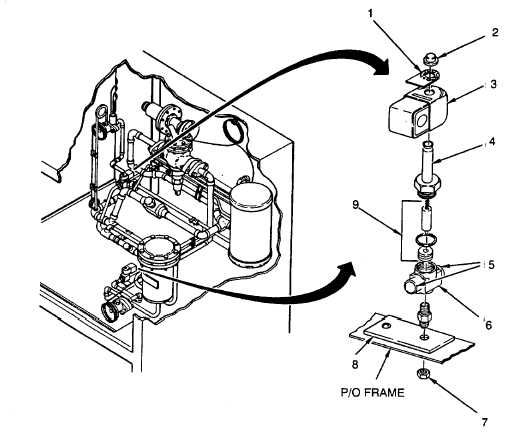
SOLENOID VALVES (L1 AND L2) - Continued. INSTALLATIION 1. Place valve body (6) in mounting position. 2. Braze tubing (5) at joints (para 5-14). 3. Install nut (7) at bottom of bracket (8). 4. Install plunger assembly (9) into tube assembly (4). 5. Install tube assembly (4). 6. Install coil (3) with nameplate (1) and retainer (2). 7. If L2 was replaced, install wiring harness with two clamps. 8. Leak test all newly connected joints and those in the repair area (para 5-15). FOLLOW ON PROCEDURE 1. Perform start up after repairs (para 5-22). 2. Close control box (para 4-45). Figure 5-24.  Solenoid Valve (L1 And L2) 5-74

Privacy Statement - Press Release - Copyright Information. - Contact Us - Support Integrated Publishing

Integrated Publishing, Inc. - A (SDVOSB) Service Disabled Veteran Owned Small Business