Order this information in Print

Order this information on CD-ROM

Download in PDF Format


Click here to make tpub.com your Home Page

Page Title: Figure 2-5. Heat Mode (Settings and Indicators)
Back | Up | Next

Click here for a printable version

Google


Web
www.tpub.com

Home


Information Categories
.... Administration
Advancement
Aerographer
Automotive
Aviation
Combat
Construction
Diving
Draftsman
Engineering
Electronics
Food and Cooking
Math
Medical
Music
Nuclear Fundamentals
Photography
Religion
USMC
   
Products
  Educational CD-ROM's
Printed Manuals
Downloadable Books


ARMY TM 9-4210-381-14 NAVY EE-000-CA-MMA-010/7053-AC AIR FORCE TO 35E9-136-31 
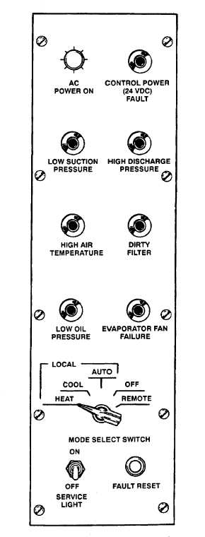
2-10.    OPERATION  IN  HEAT  MODE  (See  Figure  2- 5). a. Check that AC POWER ON light is on. CAUTION Ensure     ac     power     has     been     on     a minimum of 30 minutes for compressor crankcase heater warmup. If compressor    slugs,    turn    mode    select switch    to    OFF,    then    turn    to    AUTO position. b. Turn MODE SELECT SWITCH to HEAT. c. Check the following lights are off: · CONTROL POWER (24VDC) FAULT · LOW SUCTION PRESSURE · HIGH DISCHARGE PRESSURE · HIGH AIR TEMPERATURE · DIRTY FILTER · LOW OIL PRESSURE · EVAPORATOR FAN FAILURE NOTE If any light (except AC POWER ON) is on,   turn   MODE   SELECT   SWITCH   to OFF.  Contact unit maintenance. Figure 2-5.  Heat Mode (Settings and Indicators) 2-9

Privacy Statement - Press Release - Copyright Information. - Contact Us - Support Integrated Publishing

Integrated Publishing, Inc. - A (SDVOSB) Service Disabled Veteran Owned Small Business