Order this information in Print

Order this information on CD-ROM

Download in PDF Format


Click here to make tpub.com your Home Page

Page Title: FIGURE 4-22. Condenser motor (B2) Removal/Replacement.
Back | Up | Next

Click here for a printable version

Google


Web
www.tpub.com

Home


Information Categories
.... Administration
Advancement
Aerographer
Automotive
Aviation
Combat
Construction
Diving
Draftsman
Engineering
Electronics
Food and Cooking
Math
Medical
Music
Nuclear Fundamentals
Photography
Religion
USMC
   
Products
  Educational CD-ROM's
Printed Manuals
Downloadable Books


TM 9-4120-389-14 b. Test (Installed) (1) 
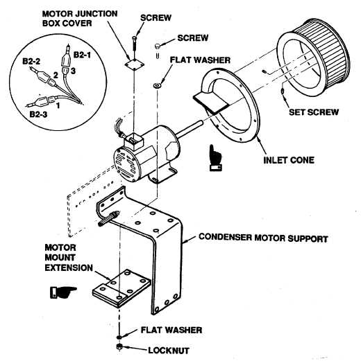
Remove four screws in motor Junction box cover. (2) Remove cover. (3) Tag and disconnect motor leads 1, 2, and 3 from harness leads B2-3, B2-2, and B2-1 respectively. (4) Using an ohmmeter or multimeter, set on lowest ohms scale, check continuity between leads 1-2, 1-3 and 2-3. Continuity should be indicated. If continuity is not indicated replace motor. (5) Check continuity between leads 1 and housing, 2 and housing and 3 and housing. Continuity should not be indicated. If continuity is indicated replace motor. c.     Removal FIGURE 4-22.    Condenser motor (B2) Removal/Replacement.   4-82   Change 1

Privacy Statement - Press Release - Copyright Information. - Contact Us - Support Integrated Publishing

Integrated Publishing, Inc. - A (SDVOSB) Service Disabled Veteran Owned Small Business