|
| |
TM 9-4120-389-14
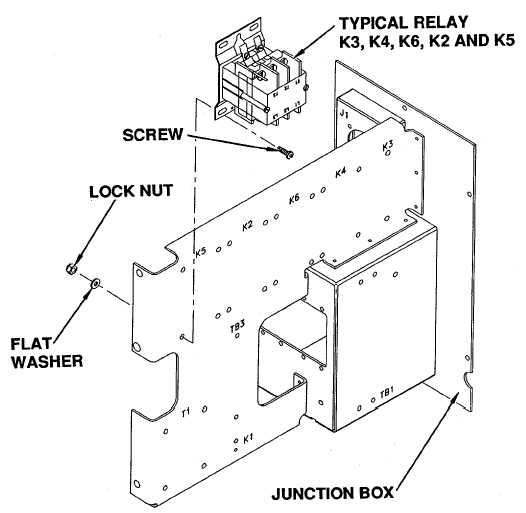
Figure 4-51. Relays K4, K6, K2 and K5
(2)
Check continuity between coil terminals X1 and X2. If there is no continuity the coil is open.
Replace the relay.
d.
Installation
(1)
Secure relay to junction box with four screws, flat washers and self locking nuts.
(2)
See wiring diagram (FO-1) and tags and connect leads.
(3)
Remove tags.
Follow-on procedure: Install junction box (See para. 4-46).
4-151
|