Order this information in Print

Order this information on CD-ROM

Download in PDF Format


Click here to make tpub.com your Home Page

Page Title: Figure 4-6. Drain Connection
Back | Up | Next

Click here for a printable version

Google


Web
www.tpub.com

Home


Information Categories
.... Administration
Advancement
Aerographer
Automotive
Aviation
Combat
Construction
Diving
Draftsman
Engineering
Electronics
Food and Cooking
Math
Medical
Music
Nuclear Fundamentals
Photography
Religion
USMC
   
Products
  Educational CD-ROM's
Printed Manuals
Downloadable Books


TM 9-4120-389-14 f.  Be sure the mode selector on the control module is in the OFF position and connect a 208 VAC, 50/60 cycle, 3 phase power to the input power connector (J-1) at the top left front corner of the unit. g.  The new unit should not require servicing, as it is shipped completely assembled and ready to operate when power is applied.  However, if any defects have been found during the inspection of the equipment they should be corrected as necessary before the unit is placed into operation. 
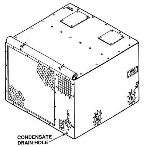
h.  Remove condensate drain plug. Connect a 1/4-18 inch NPT threaded pipe to the drain connections on the  bottom  right  rear  of  the  unit  to  remove  condensate  water.    Extend  piping  or  hose  to  deposit  water  in  a suitable location or container. Figure 4-6.  Drain Connection 4-11

Privacy Statement - Press Release - Copyright Information. - Contact Us - Support Integrated Publishing

Integrated Publishing, Inc. - A (SDVOSB) Service Disabled Veteran Owned Small Business