 |
|||
|
|
|||
|
|
|||
| ||||||||||
|
|
 TM9 4120-423-14&P
INSTALLATION
1
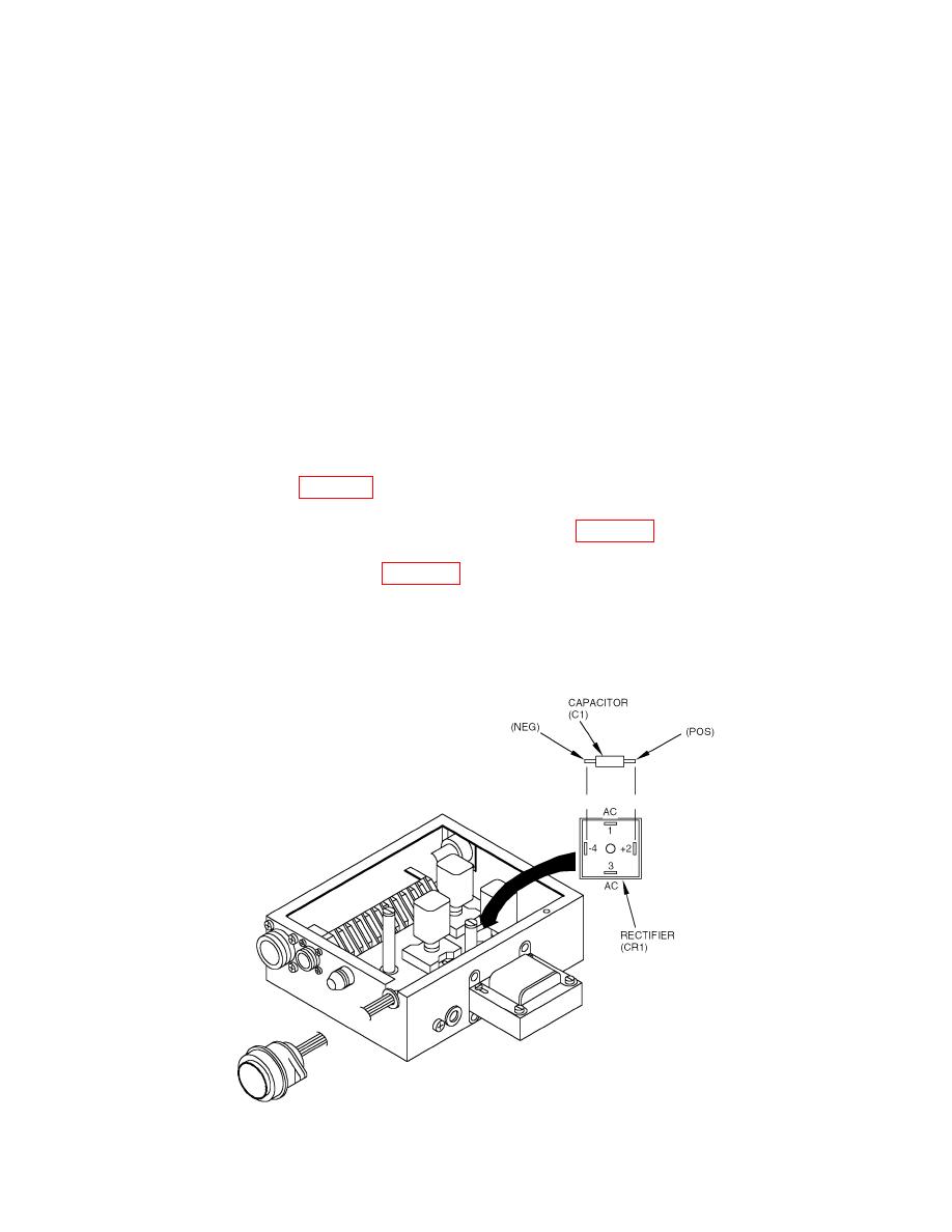
Match wire leads and capacitor to rectifier, using tags, wire markings, and wiring diagram.
2
Solder leads and capacitor to rectifier.
3
Remove tags.
4
Place rectifier in box and align hole.
5
Using screwdriver, secure rectifier with screw.
6
Place cover on box and line up holes.
7
Using screwdriver, attach the cover with six screws and lockwashers. Do not over tighten, it will
cause distortion. See WP0041.
8
Install evaporator section electrical module assembly. See WP0032.
9
Install top evaporator cover. See WP0026.
TESTING
Rectifier (CR1) and Capacitor (C1) Test
0037 00-3
|
|
Privacy Statement - Press Release - Copyright Information. - Contact Us |
