 |
|||
|
|
|||
|
|
|||
| ||||||||||
|
|
 TM 5-4110-217-14
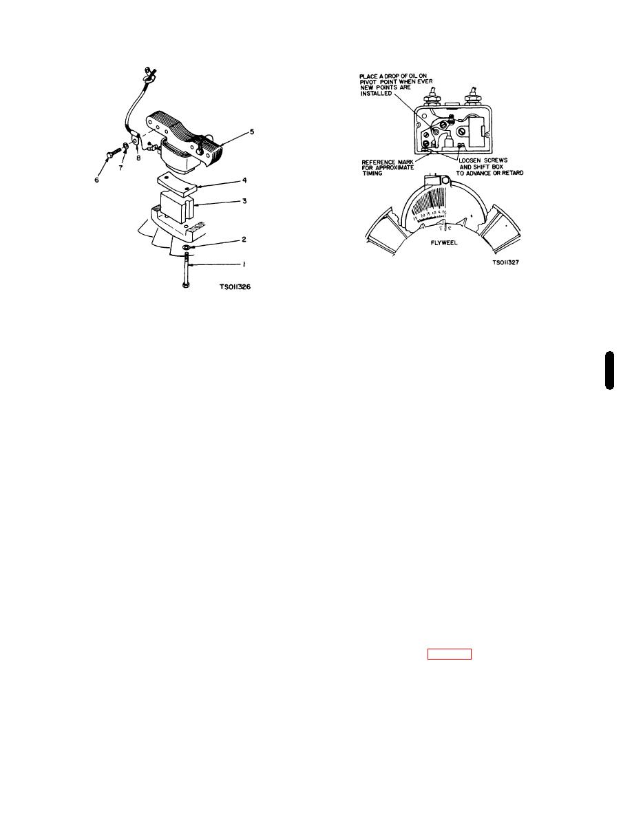
Figure 3-18. Ignition Timing
Either spark plug can be used as they fire
1.
Screw
6.
Screw
simultaneously.
2.
Washer
7.
Washer
(2) Place a white chalk or paint mark on the
3.
Spacer
8.
Clip
timing mark.
4.
Magnet
9.
Screw
(3) Start the engine and check the timing.
5.
Magneto stator assembly
Correct timing is 19 BTC.
(4)
If timing
needs adjustment, loosen the mounting screws on
Figure 3-17. Magneto
breaker box and move it left to advance or right to retard
the timing.
d. Rotate engine clockwise (facing flywheel) by
(5) Tighten the screws on the breaker box
hand until points are fully open. Turn screw (C) until
and recheck timing.
point gap measures 0.020 inch; use flat thickness
(6) Replace breaker box cover and any other
measuring gage.
hardware removed.
e. Tighten mounting screws and recheck gap.
b. Engine Not Running.
f.
Replace both spark plugs.
(1) Connect a continuity test lamp set across
the ignition breaker points. Touch one test prod to the
NOTE
breaker box terminal to which the coil lead is connected
and touch the other test prod to a good ground on the
If spark plugs have not been changed
engine.
within 200 hours of operation, replace
(2) Turn
crankshaft
against
rotation
them with new ones after setting breaker
(counterclockwise) until the points close. Then slowly
points.
turn the crankshaft with rotation (clockwise).
(3) The lamp should go out just as the points
g. Proceed to ignition timing.
break.
h.
(4) If timing needs adjustment, loosen the
3-45.
Ignition Timing.
mounting screws on breaker box and move it left to
a. Engine Running Timing. Always check timing
advance or right to retard the timing.
after replacing ignition points or if noticing poor engine
performance. Proceed as follows:
3-46.
(1) To accurately check the ignition timing,
The alternator (fig. 3-19) covered in this paragraph
using timing light when engine is running. Connect the
is designed for 12 volt negative ground electrical
timing light according to manufacturer's instructions.
systems. The mechanical construction of the alternator
differs from the DC generator in that
Change 3 3-25
|
|
Privacy Statement - Press Release - Copyright Information. - Contact Us |
