 |
|||
|
|
|||
|
|
|||
| ||||||||||
|
|
 TM5-4110-234-14
TO 40R7-5-7-1
(3)
Tag and remove the wires.
(4)
Remove the hex nut and washers that secure the switch to the panel and remove the switch.
b.
Testing.
(1) With an ohmmeter check for zero ohms resistance with the switch in the ON position (this would be
upward on the panel).
(2)
Check for infinite resistance with the switch in the OFF position (this would be downward on the panel).
c.
Installation.
(1) Position the switch on the panel with the ON position on top, but with the toggle pointing down, and
secure it to the panel with the hex nut and washers.
(2)
Connect the wire leads. See tags and wiring diagram figures 4-5 or 4-6.
(3)
Close the hinged control panel and secure with two screws and lock washers.
(4)
Connect power.
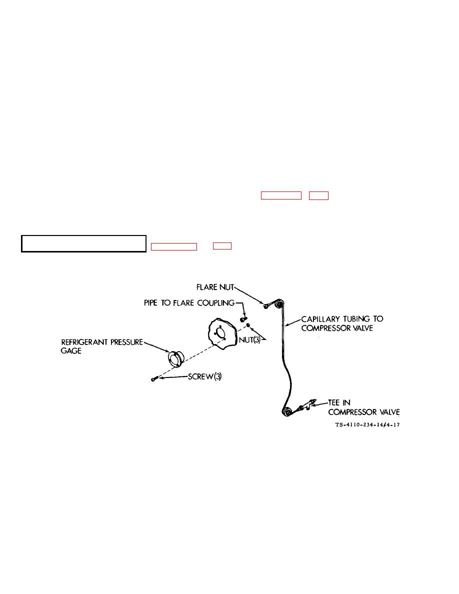
4-28.
This gage indicates the discharge pressure at the output of the compressor.
Figure 4-17. Refrigerant Pressure Gages
a.
Removal.
(1)
Disconnect power.
(2)
Open doors to have access to the left rear of the control panel and the compressor discharge valve.
(3) Remove the protective cap from the discharge valve stem. Use a refrigerant valve wrench or other
suitable wrench and totally backseat (turn fully counterclockwise) the valve.
4-40
|
|
Privacy Statement - Press Release - Copyright Information. - Contact Us |
