 |
|||
|
|
|||
|
Page Title:
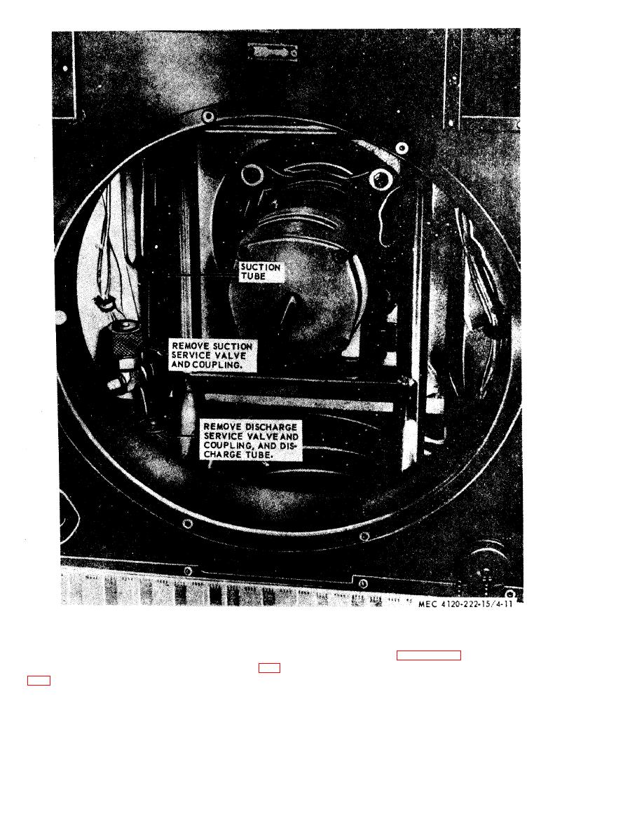
Figure 5-11. Service valves, removal and installation. |
|
||
| ||||||||||
|
|
 fully charged. See figure 526 for instructions on
Remove the two screws holding the bracket, un-
solder the sight glass connections and remove (fig.
evcuation and charging system.
5-20) .
d. Installation. Place a new liquid line sight
glass in position and solder connections. Since the
replacement glass opened the refrigerant system
the casing, directly behind the discharge grill and
the system must be completely evacuated and then
mist eliminator. The coil must be removed from
AGO 20053A
|
|
Privacy Statement - Press Release - Copyright Information. - Contact Us |
